.png)
In the realm of process automation, semiconductor manufacturing, and advanced laboratory research, the precise management of gas and liquid flow is not merely a preference; it is an absolute operational necessity. When designing fluid delivery systems, engineers are frequently confronted with a critical hardware decision: should the process rely on a Mass Flow Meter or a Mass Flow Controller? From our experience at Sino-Inst, failing to understand the specific differences between MFC and MFM architecture can lead to compromised system stability, excessive pressure drops, or highly inaccurate batch processing.

While the acronyms are frequently used interchangeably by procurement departments, the functional realities of these two instruments dictate vastly different roles within a piping and instrumentation diagram (P&ID). An MFM passively observes, while an MFC actively commands. To ensure your process achieves optimal yield and safety, we recommend a thorough evaluation of your specific flow requirements. In this authoritative technical guide, we will dissect the 5 primary differences between MFC and MFM technologies, evaluate their internal architectures, and provide clear parameters for selecting the correct instrument for your fluid mass measurement and control needs.
Table of Contents
- 1. Foundational Definitions: What is an MFM?
- 2. Foundational Definitions: What is an MFC?
- 3. The 5 Crucial Differences Between MFC and MFM
- 4. Sino-Inst Measurement Technologies and System Integration
- 5. Summary Table: Differences Between MFC and MFM
- 6. Frequently Asked Questions (FAQs)
- 7. Industry References
1. Foundational Definitions: What is an MFM?
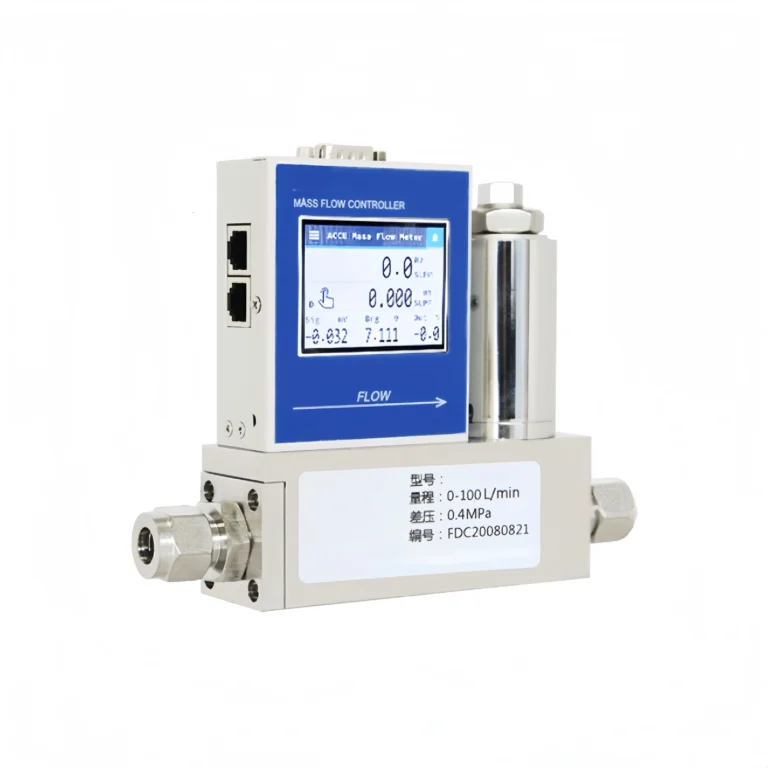
An MFM, or Mass Flow Meter, is a purely diagnostic and measurement instrument. Its sole responsibility within a fluid system is to quantify the mass of the gas or liquid passing through its internal sensor tube per unit of time (such as standard cubic centimeters per minute, sccm, or kilograms per hour). Because it relies on mass rather than volume, an MFM provides an incredibly accurate reading that remains unaffected by fluctuations in system temperature or line pressure.
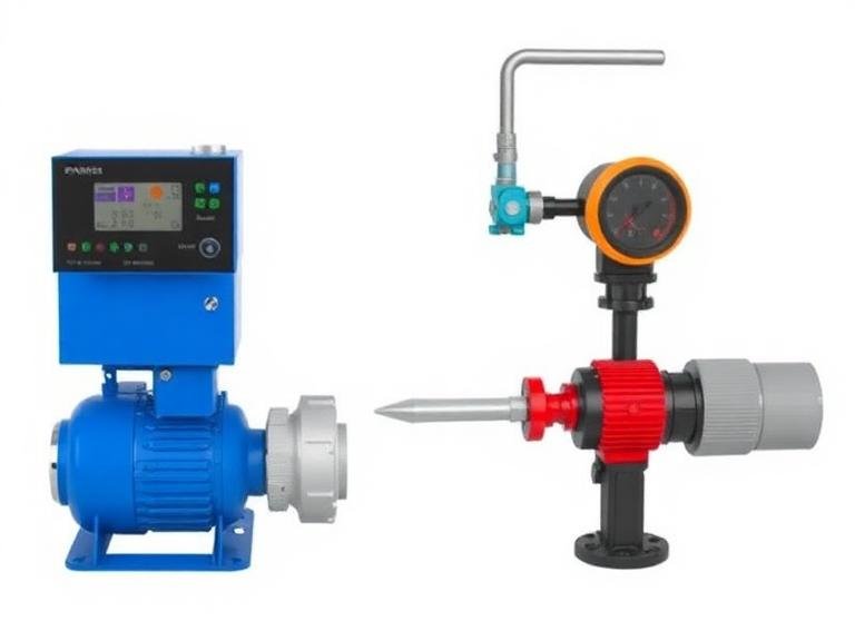
From our experience, we recommend deploying an MFM in applications where the flow is already being controlled by a separate, external mechanism—such as a variable frequency drive (VFD) pump or a downstream needle valve—and the operator simply needs to monitor or record the exact amount of fluid being transferred. An MFM acts as the eyes of your fluid delivery system, reporting data back to a central PLC or SCADA system.
2. Foundational Definitions: What is an MFC?
An MFC, or Mass Flow Controller, encompasses everything an MFM does, but takes it a massive step further by introducing autonomous physical control. An MFC is essentially an MFM integrated with a highly precise proportional control valve and a closed-loop Proportional-Integral-Derivative (PID) microprocessor.
When you input a specific setpoint into an MFC, the internal sensor measures the current flow rate, the PID controller compares that actual reading against your requested setpoint, and the circuitry instantly commands the proportional valve to open or close to match the desired rate perfectly. This closed-loop system happens in milliseconds. Therefore, an MFC is both the eyes and the hands of the fluid delivery system, actively manipulating the process environment to achieve the exact mass flow required, regardless of upstream pressure spikes or downstream resistance.
3. The 5 Crucial Differences Between MFC and MFM
Understanding the differences between MFC and MFM is critical for preventing bottlenecks and ensuring process safety. Below are the five distinct engineering variations that separate these two instruments.
Difference 1: Functional Purpose and Automation
The most defining of the differences between MFC and MFM is their ultimate purpose within a control loop. An MFM is a passive device. It sits in the pipeline and transmits an analog (e.g., 4-20mA) or digital signal representing the current flow rate. If a blockage occurs downstream and the flow slows down, the MFM will simply report the lower flow rate; it cannot do anything to correct the situation.
Conversely, an MFC is an active automation device. If the same downstream blockage occurs, the MFC’s sensor will detect the drop in flow, and the internal PID controller will automatically command the integrated proportional valve to open wider, attempting to force more gas or liquid through the line to maintain the programmed setpoint. This autonomous correction is why MFCs are mandatory in critical applications like semiconductor chemical vapor deposition (CVD) or bioreactor gas sparging.
Difference 2: Internal Hardware and Valve Integration
When you physically examine the instruments, the structural differences between MFC and MFM become immediately apparent. An MFM consists of a flow body, a flow splitter (bypass), a sensor tube, and a printed circuit board (PCB) for signal processing. It is generally compact and lightweight.
An MFC contains all the components of an MFM, plus an electromagnetic or piezoelectric proportional control valve attached to the flow body. The addition of this valve block makes the MFC physically larger, heavier, and more complex. Furthermore, the PCB inside an MFC must accommodate advanced PID control circuitry and valve-driving electronics, requiring more robust power consumption than a standard MFM.
Difference 3: Pressure Drop Dynamics
From a fluid dynamics perspective, one of the most critical differences between MFC and MFM lies in how they impact pipeline pressure. Every instrument introduced into a fluid line creates a pressure drop (Delta P). Because an MFM features an open, unobstructed flow path (aside from the laminar flow elements), its pressure drop is exceptionally low.
An MFC, however, relies on a restrictive proportional valve to regulate flow. Even when the MFC is commanded to open to 100% capacity, the internal geometry of the valve orifice creates a significant pressure drop across the device. System engineers must account for this Delta P when sizing supply pumps or gas regulators. We recommend ensuring your gas cylinder or pump can deliver a pressure substantially higher than your process pressure to overcome the natural restriction of the MFC valve.
Difference 4: Calibration and Control Loops
Calibration complexity highlights another of the differences between MFC and MFM. When calibrating an MFM, the technician only needs to verify that the sensor accurately reads the mass of the gas or liquid passing through it. The zero point and span are adjusted, and the device is ready for service.
Calibrating an MFC is a dual-layered process. First, the sensor must be calibrated exactly like an MFM. Second, the PID control loop must be tuned specifically to the dynamics of the fluid and the valve. If the PID settings are too aggressive, the valve will oscillate (hunt) around the setpoint, causing unstable flow. If the settings are too sluggish, the MFC will take too long to reach the desired flow rate. The calibration of the valve’s response time is a highly technical procedure that separates an MFC from a standard meter.
Difference 5: Cost and Application Suitability
The final aspect of the differences between MFC and MFM is the economic investment. Due to the inclusion of the precision-machined proportional valve, the actuator coil, and the advanced PID microprocessor, an MFC is significantly more expensive than an MFM of the same flow range and accuracy class.
We recommend a strategic procurement approach: do not pay for control if you only need measurement. For example, if you are monitoring the total consumption of nitrogen gas in a facility for billing purposes, an MFM is the correct, cost-effective choice. However, if you are blending precise ratios of argon and oxygen for an industrial welding process, investing in an MFC is absolutely required to ensure weld integrity.
4. Sino-Inst Measurement Technologies and System Integration
Sino-Inst’s fluid mass measurement and control products are available in three technology types: thermal, differential pressure, and Coriolis. All three types utilize proven and mature technologies, ensuring high accuracy and reliability for Sino-Inst products. To further ensure accuracy, internally compensated laminar differential pressure technology, intelligent sensor technology, and digital display technology are also widely used in the product series.
Selecting between our Mass Flow Controllers/Meters depends entirely on your process fluid. Thermal mass technology is ideal for clean, dry gases. Differential pressure (using laminar flow elements) provides ultra-fast response times for low-flow gas applications. Coriolis technology is the gold standard for high-accuracy liquid mass measurement, completely unaffected by fluid viscosity or density changes.
Furthermore, from our experience in complete plant safety, mass flow instrumentation must be integrated with environmental monitoring. When handling hazardous, combustible, or toxic gases, your MFC delivery systems must be paired with robust leak detection. We recommend integrating our Fixed Gas Detectors around your reactor vessels, supported by a central Gas Monitoring System to automatically shut off the MFCs if a leak is detected. For personnel conducting maintenance on these flow lines, Portable Gas Detectors are a mandatory safety protocol. Original equipment manufacturers (OEMs) building custom gas delivery skids frequently utilize our 800 Series Gas Sensor Module alongside our MFCs for integrated safety. Finally, for environments where particulate matter is a concern, utilizing Dust Monitors ensures that air quality remains within safe operational limits, preventing contamination of sensitive laminar flow elements.
5. Summary Table: Differences Between MFC and MFM
| Feature / Characteristic | Mass Flow Meter (MFM) | Mass Flow Controller (MFC) |
|---|---|---|
| Primary Function | Passive measurement and data reporting. | Active measurement and autonomous flow control. |
| Hardware Components | Sensor tube, bypass, signal processing board. | Sensor, bypass, PID controller board, proportional valve. |
| System Pressure Drop | Very Low (minimal flow obstruction). | High (requires pressure differential to operate valve). |
| Input Requirement | Only requires power to output a signal. | Requires power and a setpoint command (analog or digital). |
| Capital Cost | Lower cost, highly economical for monitoring. | Higher cost due to precision valve and PID circuitry. |
6. Frequently Asked Questions (FAQs)
Can I use an MFC just to measure flow without controlling it?
Yes. If you send a command to the MFC to open its valve to 100%, it will essentially act as an MFM, allowing fluid to pass through while reporting the flow rate. However, from our experience, this is an inefficient use of capital, as you are paying for an expensive valve and PID controller that you are not utilizing, and you will still suffer the pressure drop caused by the valve orifice.
How does gas density affect MFC and MFM readings?
Because thermal and Coriolis technologies measure mass directly rather than volumetric flow, they are largely immune to changes in gas density caused by pressure and temperature fluctuations. This makes both instruments vastly superior to traditional volumetric rotameters in processes where environmental conditions vary.
What is a PID controller inside an MFC?
PID stands for Proportional-Integral-Derivative. It is the mathematical algorithm used by the MFC’s onboard microprocessor to calculate exactly how far to open or close the proportional valve. It analyzes the error between the desired flow (setpoint) and the actual flow, ensuring the valve reaches the target quickly without overshooting.
7. Industry References
- International Society of Automation (ISA) – Standards for Process Control and Instrumentation
- National Institute of Standards and Technology (NIST) – Fluid Metrology and Mass Flow Standards
- U.S. Department of Energy (DOE) – Advanced Manufacturing Process Control
By clearly understanding the differences between MFC and MFM technologies, process engineers can design highly efficient, cost-effective, and safe fluid delivery architectures. At Sino-Inst, we are committed to providing the exact measurement and control instrumentation required to optimize your industrial applications.