.png)
In modern industrial manufacturing, laboratory research, and specialized fluid handling, achieving absolute precision is not a luxury; it is a fundamental requirement. Whether you are managing the deposition of reactive gases in semiconductor fabrication, regulating the fuel cell gas supply, or overseeing biotechnology incubation, learning how to correctly use a mass flow controller is critical to your process stability. Operating these sophisticated instruments requires more than simply connecting a tube and applying power. It demands a rigorous understanding of fluid dynamics, electrical signal integrity, and strict installation protocols.
Sino-Inst is a professional supplier of industrial process and analytical instruments, including gas detectors, gas analyzers, dust detectors, mass flow controllers, and dust monitors. We can help you obtain reliable measurement and analysis solutions while saving procurement costs. Customized products and OEM services are available. We will be your most trusted partner! From our experience equipping laboratories and heavy industries across the globe, we frequently encounter process errors that stem directly from improper installation or operation. In this comprehensive, step-by-step guide, we will outline the exact procedures you must follow to successfully use a mass flow controller, ensuring optimal accuracy, prolonged equipment lifespan, and uncompromising safety.
Table of Contents
- 1. Understanding the Anatomy Before You Use a Mass Flow Controller
- 2. Preparation and Essential Safety Protocols
- 3. Step-by-Step: How to Use a Mass Flow Controller
- 4. Advanced Best Practices to Use a Mass Flow Controller Accurately
- 5. Sino-Inst: Your Trusted Partner in Precision Flow Control
- 6. Summary Table: Quick Reference for MFC Operation
- 7. Frequently Asked Questions (FAQs)
- 8. Industry References
1. Understanding the Anatomy Before You Use a Mass Flow Controller
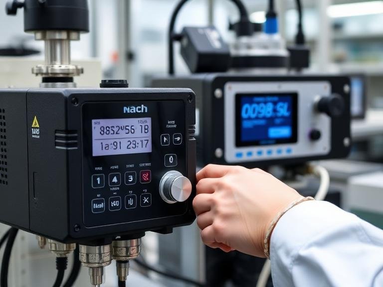
Before you attempt to use a mass flow controller, it is essential to understand how it differs from a simple mass flow meter. A mass flow meter only measures the mass of the fluid passing through it and outputs a signal. A mass flow controller, however, incorporates a highly responsive proportional control valve and a PID (Proportional-Integral-Derivative) control circuit. When you use a mass flow controller, the internal sensor constantly measures the flow rate, compares it to the setpoint you have dictated, and automatically adjusts the control valve to eliminate any deviation.
Most industrial controllers utilize either thermal mass flow sensing or differential pressure sensing. Regardless of the internal physics, the operational methodology remains similar. Because these devices contain delicate internal capillaries, sensors, and actuator valves, rough handling or improper startup sequences can instantly ruin calibration. To use a mass flow controller effectively, you must treat it as a sensitive electronic instrument rather than a standard piece of plumbing hardware.
2. Preparation and Essential Safety Protocols
Safety and environmental control must be your first priorities when preparing to use a mass flow controller. Many of the reactive, corrosive, or toxic gases managed by these devices pose severe health risks. We recommend donning appropriate Personal Protective Equipment (PPE) and ensuring adequate ventilation before interacting with any process gas lines.
Furthermore, because the internal circuitry is highly sensitive, Electrostatic Discharge (ESD) is a significant threat. Before handling the device, you should wear a grounded anti-static wrist strap. Ensure that all power is disconnected from the supply line before performing any wiring. Finally, verify that your piping diameter matches the fittings on your controller. Typical piping diameters include 1/4 inch (approximately 6.35 mm), but 1/8 inch, 3/8 inch, and 1/2 inch are also common depending on the flow volume. Attempting to force unmatched fittings is a guaranteed way to induce dangerous system leaks.
3. Step-by-Step: How to Use a Mass Flow Controller
To guarantee peak accuracy and safety, we have developed a strict, sequential protocol. Follow these expert steps every time you install and use a mass flow controller in your facility.
Step 1: Mechanical Installation and Piping Alignment
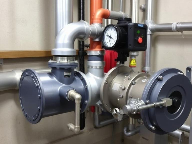
To use a mass flow controller, you must first integrate it into your fluid line. Identify the flow direction arrow engraved or printed on the body of the instrument; the controller will only function if installed in this specific orientation. Depending on your model, you will typically encounter either VCR fittings or Swagelok (compression) fittings.
For VCR fittings, place a new, unscratched metal gasket between the male and female fittings. Tighten the nut by hand, and then use a wrench to tighten it a further 1/8 turn. For Swagelok compression fittings, slide the nut and ferrule over the tubing, insert the tube fully into the fitting body, and tighten the nut to the manufacturer specified torque (often 1-1/4 turns past finger-tight). Ensure the piping is completely straight and properly supported; the controller should never bear the structural weight of the surrounding pipes.
Step 2: Performing a Rigorous Leak Check
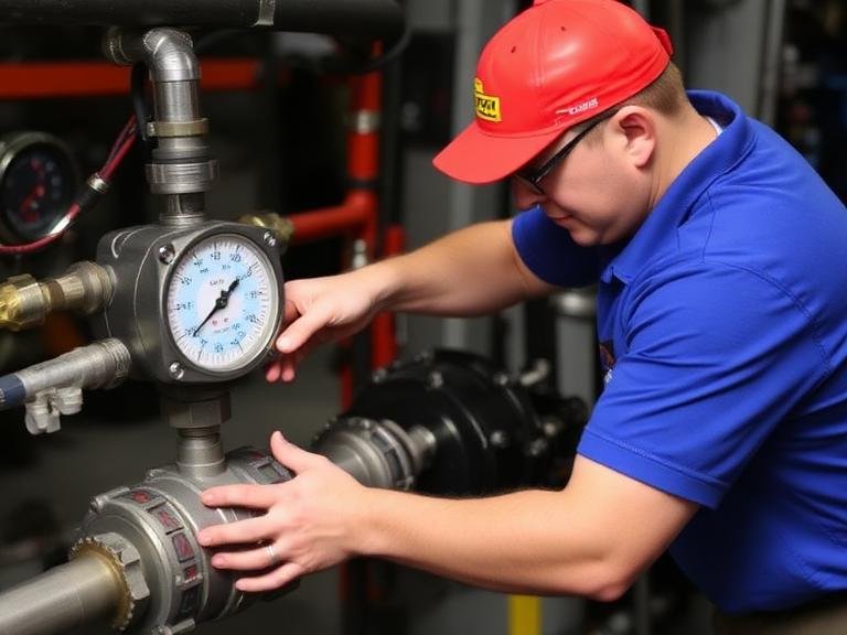
Never bypass this step when you use a mass flow controller. Before applying electrical power or introducing hazardous process gases, you must verify the integrity of your mechanical seals. Slowly pressurize the system using a safe, inert gas such as nitrogen or helium. Apply an approved liquid leak detector solution to the inlet and outlet joints and watch for bubbles. For ultra-high purity systems, we recommend using a helium mass spectrometer leak detector to guarantee absolute hermetic integrity.
Step 3: Electrical Connections and Signal Shielding
To use a mass flow controller properly, stable power and clear signal communication are mandatory. Consult your specific instruction manual for the correct pinout configuration (often a 9-pin or 15-pin D-sub connector). Supply the required DC voltage (typically 15V to 24V).
From our experience, poor wiring is the leading cause of erratic flow readings. When you use a mass flow controller, you must keep signal cables as short as possible to prevent voltage drop, which can degrade the 0-5V or 4-20mA setpoint signals. Always use shielded cables, and terminate the shield to an earth ground at one end to prevent electromagnetic interference (EMI). Crucially, do not cross-wire the power supply common, the setpoint signal common, and the output signal common unless explicitly instructed by the wiring diagram.
Step 4: The Crucial Warm-Up Period
A common mistake novice operators make when they use a mass flow controller is expecting instant accuracy the moment power is applied. Thermal mass flow sensors operate by measuring heat transfer, which requires the sensor tube to reach a stable internal temperature. After turning on the power supply, you must allow the instrument to warm up for a minimum of 30 minutes. During this period, keep the process gas valves completely closed.
Step 5: Zero-Point Calibration
Over time, shifts in ambient temperature or installation position can cause a slight deviation in the zero reading. To use a mass flow controller with maximum precision, you must reset the zero point before initiating flow. Ensure the upstream and downstream valves are completely shut so there is absolutely zero gas movement through the device. Activate the zero-reset function via your digital interface or by pressing the physical zero button on the device. Wait for the output signal to stabilize at exactly 0.00.
Step 6: Setting the Flow Rate and Initiating the Process
With the device warmed up and zeroed, you are ready to use a mass flow controller to govern your process. Slowly open the upstream process valves to apply differential pressure across the controller. Opening valves too quickly can cause a massive pressure surge that may damage the delicate sensor bypass structure. Once the supply pressure is stable, use your digital interface, PLC, or analog dial to input your desired flow rate setpoint. The internal PID loop will immediately take over, opening the proportional valve to match your exact requested flow rate.
4. Advanced Best Practices to Use a Mass Flow Controller Accurately
To ensure long-term stability and reliability when you use a mass flow controller, specific operational parameters must be maintained. The most critical factor is supply pressure stability. If your upstream gas cylinder or compressor fluctuates wildly, the PID controller will struggle to maintain a stable output. We recommend installing a high-quality pressure regulator immediately upstream of the controller to provide a constant, unwavering inlet pressure.
Additionally, when you use a mass flow controller for easily liquefiable gases, you must remain vigilant against cold spots. As gas expands through the control valve, the Joule-Thomson effect can cause a rapid drop in temperature, potentially causing the gas to re-liquefy inside the instrument. This will instantly trigger erratic flow readings and physical damage. To prevent this, we recommend utilizing heat tracing on the piping and maintaining the ambient environment above the gas dew point.
5. Sino-Inst: Your Trusted Partner in Precision Flow Control
Understanding how to use a mass flow controller is only half the battle; acquiring high-quality instrumentation is equally vital. Sino-Inst is a professional supplier of industrial process and analytical instruments. We can help you obtain reliable measurement and analysis solutions while saving procurement costs. Customized products and OEM services are available. We will be your most trusted partner! Our extensive catalog is engineered to meet the highest global standards of accuracy and durability.
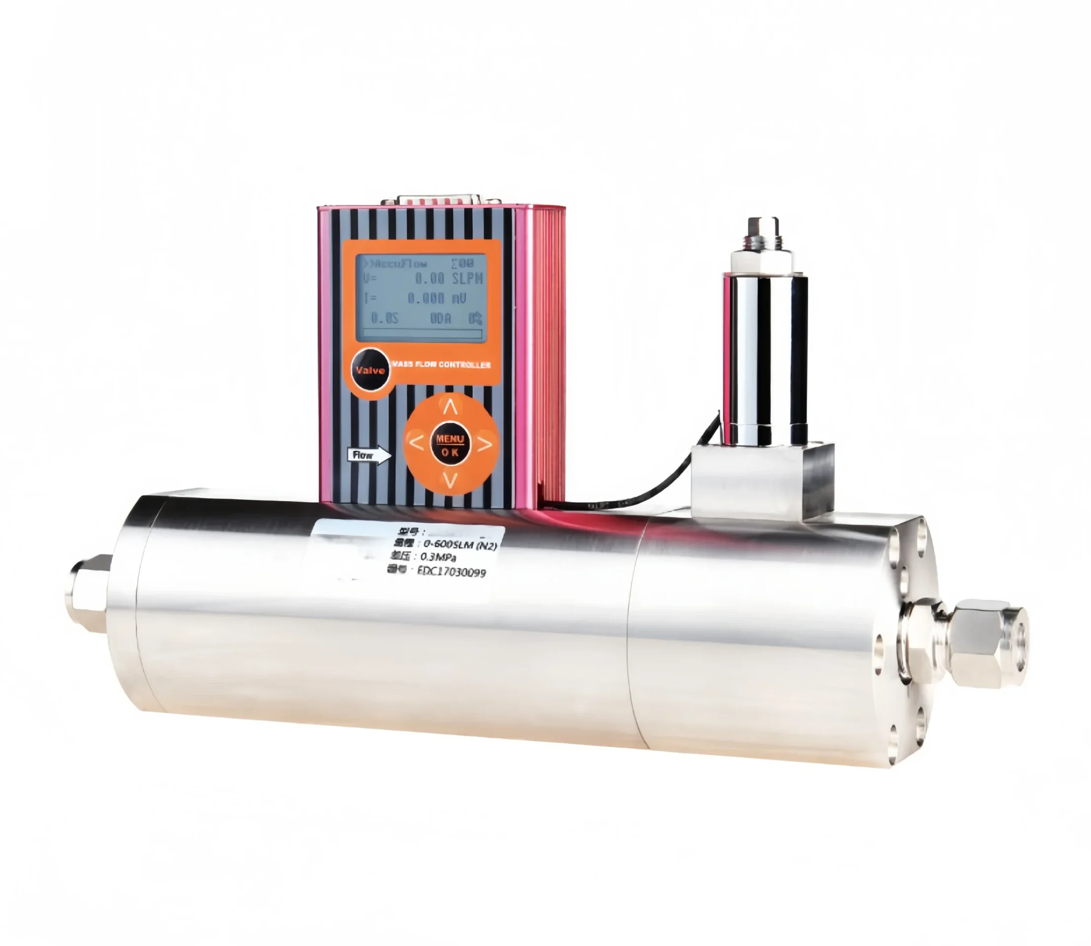
For applications demanding advanced digital communication and localized displays, our SI-10FD Digital Mass Flow Controller/Meter offers exceptional stability and intuitive operation. If your process involves incredibly strict tolerances and minimal pressure drop allowances, we recommend the SI-20FDR Gas Mass Flow Controller | High Accuracy – Low Differential Pressure, which delivers unparalleled performance in critical semiconductor and vacuum coating applications. For laboratory environments where space is a premium, our SI-30FC Compact DP Mass Flow Controller for Gases provides robust, high-speed differential pressure flow control in a remarkably small footprint.
6. Summary Table: Quick Reference for MFC Operation
To assist technicians and engineers on the floor, we have compiled this quick-reference checklist to follow every time you install and use a mass flow controller.
| Operational Phase | Action Required | Why It Is Critical |
|---|---|---|
| Mechanical Setup | Verify flow direction, connect matching fittings (VCR/Swagelok), tighten to spec. | Prevents destructive leaks and ensures the sensor operates in the correct vector. |
| Leak Testing | Pressurize with inert gas and use liquid detector or helium mass spectrometer. | Protects operator safety and prevents atmospheric contamination of process gases. |
| Electrical Wiring | Use shielded cables, ground the shield, isolate common grounds. | Prevents electromagnetic interference (EMI) and signal voltage drops. |
| Warm-Up | Apply power and wait 30 minutes before flowing gas. | Allows thermal sensors and internal circuitry to reach operational equilibrium. |
| Zero Calibration | Ensure absolutely no gas flow, then trigger the zero-reset function. | Eliminates baseline drift caused by installation orientation or ambient temperature. |
| Flow Initiation | Open upstream valves slowly; input the desired setpoint. | Prevents mechanical shock to the sensor bypass and enables smooth PID regulation. |
7. Frequently Asked Questions (FAQs)
Do I need to recalibrate when I use a mass flow controller for a different gas?
Yes. Thermal mass flow controllers rely on the specific heat capacity of the fluid. If your device was calibrated for Nitrogen and you attempt to use it for Helium, the output reading will be entirely inaccurate. You must either utilize a conversion factor (if supported by your specific model) or send the unit back to the manufacturer for precise physical recalibration.
Why does the flow rate fluctuate when I use a mass flow controller?
Flow fluctuation is typically caused by unstable upstream supply pressure, electrical interference on unshielded signal cables, or liquid condensation within the gas line. Ensure your pressure regulator is functioning correctly and check that your signal cables are short and properly grounded.
Can I use a mass flow controller to regulate liquid flow?
It depends heavily on the model. While the operational logic is similar, standard gas mass flow controllers cannot be used for liquids, as the density and thermal properties will damage the sensor and valve. You must select a dedicated Liquid Mass Flow Controller specifically engineered for your fluid.
How often should I service or calibrate my mass flow controller?
From our experience at Sino-Inst, we recommend an annual factory calibration to maintain maximum accuracy, especially in critical industries like biopharmaceuticals or semiconductor manufacturing. Regular maintenance ensures the internal sensors are free of particulate buildup and the valve actuators remain responsive.
8. Industry References
To further enhance your understanding of fluid dynamics, precision measurement standards, and advanced instrumentation protocols, we recommend reviewing the following authoritative resources: