.png)
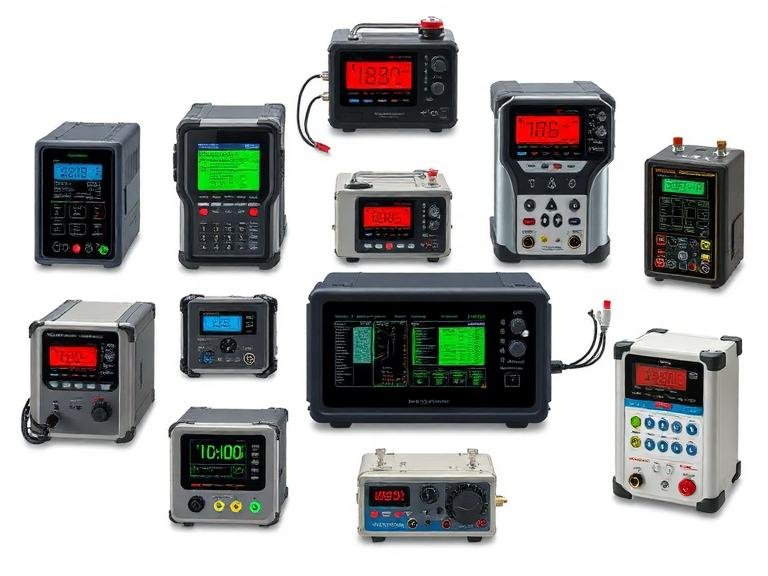
The effective implementation of industrial gas detection systems represents a foundational pillar of modern occupational safety and environmental stewardship. We will examines the multifaceted process of selecting, installing, and maintaining these protective networks, with a specific focus on fixed gas monitoring systems.
By analyzing key hazard assessments of specific locations, the selection of target gases and the installation location of detectors were determined. We will conduct a comparative analysis of various sensor technologies, including electrochemical, catalytic, infrared, and photoionization technologies.
Of course, to ensure the long-term reliability and effectiveness of stationary gas detection systems, a comprehensive approach must be adopted, taking into account environmental factors, maintenance procedures, and data management.
Imperative of Gas Detection
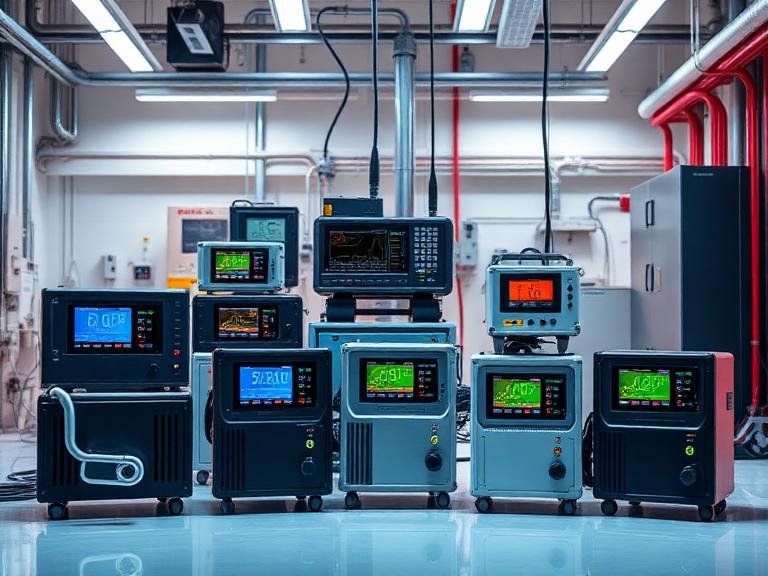
In the intricate tapestry of industrial operations, from the sprawling complexes of petrochemical refining to the meticulous environments of pharmaceutical manufacturing, a silent, invisible threat often pervades the atmosphere. The presence of toxic or combustible gases is not merely a technical problem to be solved; it is a profound ethical and practical challenge that touches upon the safety of every individual within a facility.
The deployment of a robust gas detection system is, therefore, not a matter of mere compliance but an expression of a fundamental commitment to human safety. It is an acknowledgment that the air we breathe, so often taken for granted, can become a vector of immense harm if left unmonitored. To think about a fixed gas monitoring system is to think about foresight, responsibility, and the technological embodiment of a precautionary principle that safeguards lives before disaster has a chance to strike.
This guide embarks on a detailed exploration of the considerations that underpin the selection of an appropriate industrial gas detection system.
Our journey will take us through the science of sensor technology, the logic of system architecture, the language of regulatory standards, and the practical economics of long-term ownership. By engaging with these facets in a thoughtful, structured manner, we can empower engineers, safety managers, and decision-makers to create environments where people can work with confidence, secure in the knowledge that a vigilant, silent guardian is always on watch.
1. Assess Your Specific Risks and Target Gases
The first movement in the symphony of designing a safe industrial environment is a deep, resonant understanding of the specific risks inherent to that space. Before one can even begin to contemplate the hardware of a gas detection system, a thorough and introspective hazard analysis must be conducted. This process is not a mere formality; it is the very foundation upon which all subsequent decisions rest.
A flaw in this initial assessment will propagate through the entire system, potentially rendering it ineffective when it is needed most. The task requires a combination of empirical knowledge of chemical processes, imaginative foresight into potential failure modes, and a sober appreciation for the consequences of an oversight.
Understanding the Nature of Gaseous Hazards
Gases present a unique challenge due to their physical properties. They are often colorless and odorless, capable of expanding to fill any volume, and can travel far from their source, carried by air currents. The hazards they pose can be broadly categorized into three domains: toxicity, flammability, and asphyxiation.
Toxic Gases:
These substances interfere with the body’s normal biochemical functions. The effect can be acute, causing immediate harm after a short exposure, or chronic, leading to long-term health issues after repeated low-level exposures. A classic example is hydrogen sulfide (H₂S), a common byproduct in oil and gas operations, which can be lethal at concentrations of a few hundred parts per million (ppm). Another is carbon monoxide (CO), the product of incomplete combustion, which dangerously binds to hemoglobin in the blood, preventing oxygen transport.
Understanding the specific toxicological profile of each potential gas in your facility is paramount. One must ask: what is the mechanism of harm? How quickly does it act? What are the recognized exposure limits? Regulatory bodies like the Occupational Safety and Health Administration (OSHA) in the United States establish Permissible Exposure Limits (PELs), often expressed as a Time-Weighted Average (TWA) over an 8-hour workday, or as a Short-Term Exposure Limit (STEL) for a 15-minute period. These values provide critical thresholds for alarm settings in a fixed gas detector system.
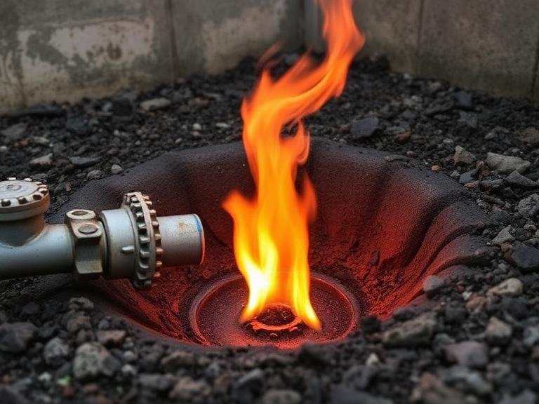
Combustible Gases:
These gases and vapors, when mixed with an oxidant (typically oxygen in the air) in the right proportion and introduced to an ignition source, can result in a fire or explosion. Methane (CH₄), propane (C₃H₈), and hydrogen (H₂) are common examples.
The danger of these gases is defined by their flammability range, which is bounded by the Lower Explosive Limit (LEL) and the Upper Explosive Limit (UEL). Below the LEL, the mixture is too “lean” to burn; above the UEL, it is too “rich.” The most dangerous condition is within this range. Consequently, industrial gas detection systems for combustibles are almost always configured to alarm at a small fraction of the LEL, typically 10-20%, to provide an early warning long before a concentration approaches a truly explosive level.
Asphyxiant Gases:
While some gases are directly toxic, others cause harm by displacing oxygen. These are known as simple asphyxiants.
Nitrogen (N₂), which makes up about 78% of the air we breathe, is harmless in that context. However, a large leak of pure nitrogen into a confined space can rapidly reduce the oxygen concentration from its normal level of 20.9% to a level that cannot sustain consciousness or life. Carbon dioxide (CO₂), while having some toxic properties at high concentrations, also acts as an asphyxiant. A fixed gas monitoring system in areas where inert gases are used or stored should therefore include sensors for oxygen deficiency.
Conducting a Site-Specific Hazard and Operability Study (HAZOP)
To systematically identify these risks, a formal process is required. The Hazard and Operability (HAZOP) study is a widely accepted methodology. It involves a multidisciplinary team of engineers, operators, and safety professionals who meticulously examine the process and instrumentation diagrams (P&IDs) of a facility. The team applies a series of “guidewords” (e.g., No, More, Less, Reverse) to process parameters (e.g., Flow, Pressure, Temperature) to brainstorm potential deviations from the design intent and their consequences.
Imagine the team examining a pipeline carrying ammonia. They might ask: What happens if there is “No Flow”? This could indicate a blockage. What happens if there is “More Flow” or “More Pressure”? This could lead to a rupture of a seal or gasket.
For each deviation, the team identifies the potential consequences, such as the release of toxic ammonia gas. They then assess the existing safeguards, like pressure relief valves, and determine if additional measures are needed. The output of a HAZOP study is a detailed list of potential gas leak scenarios, their locations, and their potential severity. This document becomes the essential blueprint for designing the gas detection system. It tells you what you need to detect and where you need to detect it.
Mapping Detector Locations Based on Gas Properties
Once the target gases are identified, the question becomes where to place the detectors. This is not a matter of guesswork; it is a science governed by the physical properties of the gases themselves. The key property to consider is vapor density, which is the density of a gas relative to air.
- Gases Lighter Than Air (Vapor Density < 1.0): Gases like methane (vapor density ≈ 0.55) and hydrogen (vapor density ≈ 0.07) will rise when released. For these gases, detectors should be placed at high points, such as near the ceiling of an enclosure or above potential leak sources like valve bonnets or flanges on a compressor station. The goal is to catch the rising gas cloud as it accumulates.
- Gases Heavier Than Air (Vapor Density > 1.0): Gases like propane (vapor density ≈ 1.56) and hydrogen sulfide (vapor density ≈ 1.19) are denser than air and will sink. They will flow along the ground and collect in low-lying areas like pits, trenches, or sumps. For these gases, detectors must be mounted low to the ground, typically 30-50 centimeters (12-20 inches) from the floor, to provide the earliest possible warning. Placing a detector for H₂S on the ceiling would be a grave and potentially fatal error.
The placement strategy must also account for ventilation patterns. Air currents, whether from natural breezes in an outdoor facility or from HVAC systems indoors, can significantly influence the dispersion of a gas cloud. Smoke studies or computational fluid dynamics (CFD) modeling can be invaluable tools for visualizing these airflows and optimizing detector placement to ensure that a leak is detected reliably, regardless of the prevailing wind direction. The goal is to place detectors in the path a gas cloud is most likely to travel, intercepting it before it can reach a large area or an ignition source.
2. Evaluate Sensor Technologies and Their Suitability
With a clear map of the risks and required detection locations, the next intellectual challenge is to select the appropriate sensor technology. This is perhaps the most technical part of the selection process, as each technology operates on a different scientific principle, bringing with it a unique set of capabilities and limitations. Choosing a sensor is not like choosing a brand of coffee; it is like a specialist choosing the right diagnostic imaging technique—MRI, CT scan, or X-ray—based on the specific condition being investigated. An industrial gas detection system is only as good as the sensing element at its heart.
There are several mature technologies available, each suited for different gases and applications. The four most common types used in fixed gas monitoring systems are catalytic bead, electrochemical, non-dispersive infrared (NDIR), and photoionization (PID).
Catalytic Bead (Pellistor) Sensors
Catalytic bead sensors are the workhorses for detecting combustible gases. Their design is elegantly simple. It consists of two small ceramic beads, or “pellistors,” one of which is coated with a catalyst (the active bead) while the other is inert (the reference bead). Both beads are heated to a high temperature (around 500°C) and form two arms of a Wheatstone bridge circuit.
Think of it like two tiny, identical stovetop burners. When a combustible gas, like methane, comes into contact with the hot, catalyzed bead, it combusts or “burns” on the surface. This combustion releases heat, causing the temperature of the active bead to increase. This temperature rise, in turn, increases the electrical resistance of the platinum wire coil embedded within it. The reference bead, being inert, does not cause combustion and its temperature and resistance remain unchanged. The Wheatstone bridge circuit measures this difference in resistance between the active and reference beads. This difference is directly proportional to the concentration of the combustible gas present, which is then displayed as a percentage of the LEL.
The primary advantage of catalytic sensors is their broad-range detection capability. They can “see” a wide variety of combustible hydrocarbons. They are also relatively inexpensive and have a long and proven track record in industry. However, they have notable vulnerabilities. They require oxygen to operate, as combustion cannot occur without it. This makes them unsuitable for inert atmospheres. They are also susceptible to “poisoning” by substances like silicones, leaded compounds, and sulfur-containing gases, which can coat the catalyst and render it inactive. They can also be damaged by exposure to very high gas concentrations, which can “burn out” the bead.
Electrochemical Sensors
Electrochemical sensors are the dominant technology for detecting a wide range of toxic gases (like CO, H₂S, Cl₂, NH₃) as well as oxygen. An electrochemical sensor can be thought of as a tiny, gas-specific fuel cell. It typically consists of two or three electrodes (a sensing electrode, a counter electrode, and sometimes a reference electrode) immersed in an electrolyte. The electrodes are separated from the ambient air by a gas-permeable membrane.
When the target gas diffuses into the sensor, a specific chemical reaction—either oxidation or reduction—occurs at the sensing electrode. For example, in a carbon monoxide sensor, CO is oxidized to CO₂. This reaction generates a small electrical current. The magnitude of this current is directly proportional to the concentration of the gas. The electronics within the gas detector measure this current and translate it into a ppm reading.
The great strength of electrochemical sensors is their high sensitivity and specificity. They can detect toxic gases at very low concentrations, often in the single-digit ppm range. By carefully selecting the electrode materials, the electrolyte, and the bias voltage, manufacturers can make sensors that are highly selective for a particular gas, minimizing cross-interference from other gases. They consume very little power and can operate in oxygen-deficient environments. Their main limitations are a finite lifespan, as the electrolyte can dry out or be consumed over time (typically 2-3 years), and their performance can be affected by significant changes in temperature and humidity. They also have a limited range and cannot be used for detecting high concentrations.
Non-Dispersive Infrared (NDIR) Sensors
Infrared (IR) sensors operate on a completely different principle: the absorption of light. Many gases, particularly hydrocarbons (like methane) and carbon dioxide, have a unique property—they absorb infrared radiation at specific wavelengths. An NDIR sensor exploits this property.
The sensor contains an infrared lamp, a sample chamber, and an infrared detector with an optical filter. A beam of IR light is passed through the sample chamber, into which the ambient air diffuses. The optical filter is chosen to match the specific wavelength of light that is absorbed by the target gas. If the target gas is present in the chamber, it will absorb some of the IR light. The detector measures the amount of light that reaches it. The difference between the amount of light emitted by the lamp and the amount received by the detector is a measure of the gas concentration.
IR sensors offer significant advantages. They are immune to sensor poisoning and are not damaged by high gas concentrations. They do not require oxygen to operate, making them ideal for both combustible gas detection in inert atmospheres and for measuring high concentrations of CO₂. They are also very stable and require less frequent calibration than other sensor types. Their primary disadvantages are that they cannot detect hydrogen (as H₂ does not absorb IR radiation) and their initial cost is typically higher than catalytic sensors. They are also only effective for gases that absorb in the infrared spectrum.
Photoionization Detectors (PID)
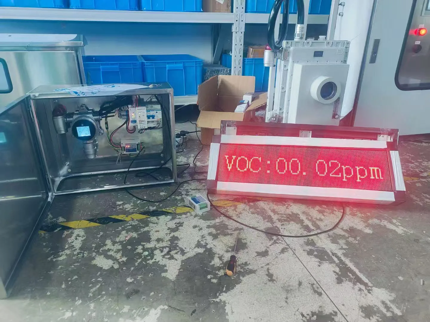
Photoionization detectors are used for detecting a broad range of volatile organic compounds (VOCs) at very low levels. VOCs are a class of chemicals, such as benzene, toluene, and xylene, that are often toxic even at trace concentrations.
A PID works by using a high-energy ultraviolet (UV) lamp to ionize the gas molecules. The lamp emits photons with enough energy to knock an electron off a VOC molecule, creating a positively charged ion. This process is called photoionization. These ions are collected on an electrode, which generates a current that is proportional to the concentration of the VOC.
The key parameter for a PID is the energy of its UV lamp, measured in electron volts (eV). A common lamp is a 10.6 eV lamp. This lamp can detect any compound with an ionization energy less than or equal to 10.6 eV. This makes PIDs excellent broad-spectrum detectors for many hazardous VOCs. Their ability to detect down to parts-per-billion (ppb) levels is unmatched by other technologies. However, this broad-spectrum nature is also a weakness: PIDs are not specific. They cannot distinguish between different VOCs. An alarm from a PID indicates the presence of something, but it doesn’t identify what it is. They are also sensitive to humidity and require frequent cleaning of the lamp.
| Sensor Technology | Principle of Operation | Primary Target Gases | Key Advantages | Key Limitations |
| Catalytic Bead | Catalytic oxidation on a heated bead | Combustible Gases (%LEL) | Low cost, robust, detects a wide range of combustibles. | Requires oxygen, susceptible to poisoning, can be burned out by high concentrations. |
| Electrochemical | Electrochemical reaction (oxidation/reduction) | Toxic Gases (ppm), Oxygen (%) | High sensitivity, good specificity, low power consumption. | Limited lifespan (2-3 years), cross-sensitivity issues, affected by temperature/humidity. |
| Infrared (NDIR) | Absorption of infrared light at a specific wavelength | Hydrocarbons (%LEL, %Vol), CO₂ | Immune to poisoning, long life, low maintenance, works in inert atmospheres. | Cannot detect hydrogen, higher initial cost, only for IR-absorbing gases. |
| Photoionization (PID) | Ionization of gas by a UV lamp | Volatile Organic Compounds (VOCs) (ppm, ppb) | Extremely sensitive to VOCs, fast response time. | Non-specific, affected by humidity, requires frequent cleaning. |
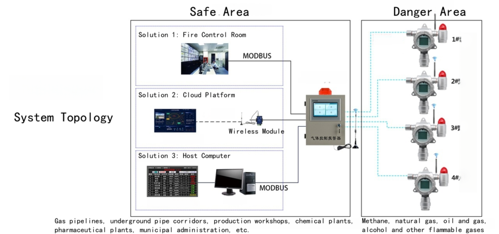
3. Determine System Architecture: Standalone vs. Integrated
Once the “what” (target gas) and the “how” (sensor technology) have been established, the next logical step is to design the “where” and “with what” of the system’s overall structure. The architecture of a gas detection system is not a one-size-fits-all proposition. It must be tailored to the scale of the facility, the complexity of the processes, the number of detection points, and the desired level of interaction with other plant safety and control systems.
The choice fundamentally revolves around whether to use a series of standalone detectors, a fully integrated system tied into a central controller, or a hybrid approach. This decision has profound implications for how alarms are annunciated, how data is managed, and how an emergency response is coordinated.
Standalone Detectors
The simplest architectural form is the standalone detector. In this configuration, each gas detector is a self-contained unit. It has its own sensor, electronics, and local alarm indicators, such as a bright flashing strobe light and a loud audible horn. When a hazardous gas concentration is detected, the unit itself goes into alarm, providing an immediate, localized warning to personnel in the immediate vicinity.
This approach is often suitable for smaller applications or for monitoring isolated, specific hazards. For example, a single standalone carbon monoxide detector could be placed near a boiler room, or a standalone ammonia detector could be used in a refrigeration equipment room. The primary advantage is simplicity. Installation is straightforward, often requiring only a power source. There is no need for complex wiring back to a central control room or for sophisticated programming.
However, the limitations of this architecture become apparent as the scale of the operation grows. In a large facility with dozens or hundreds of detection points, relying solely on local alarms is untenable. An alarm might go off in a remote, unoccupied area, and no one would know. There is no central point of visibility or control. Responding to an incident becomes a challenge, as emergency personnel would have no immediate information on the location or nature of the gas leak. Data logging is also typically minimal or non-existent, making incident investigation and trend analysis difficult.
Centralized, Integrated Systems
For most industrial facilities of any significant size, a centralized, integrated architecture is the standard. In this model, each gas detector (or “transmitter”) is a field device that senses the gas and transmits its reading back to a central gas controller or a plant-wide Distributed Control System (DCS) or Safety Instrumented System (SIS).
This architecture creates a single, unified point of command and control. Operators in a central control room can view the status of every single gas detector in the plant on a single screen. They can see real-time gas concentrations, detector statuses (e.g., normal, fault, alarm), and historical trends. When a detector goes into alarm, it is immediately flagged on the central system, showing the precise location and gas level.
This centralized awareness is transformative for safety management. It allows for a coordinated, intelligent response. Instead of just a local horn, the central system can be programmed to trigger a sophisticated cause-and-effect matrix of actions. For example, a high-level combustible gas alarm could automatically:
- Trigger plant-wide evacuation sirens.
- Activate deluge systems or fire suppression equipment.
- Shut down a specific process unit by closing emergency shutdown valves (ESDs).
- Turn on ventilation fans to help disperse the gas cloud.
- Close fresh air intakes for buildings to prevent gas from being drawn inside.
The integration with a DCS or SIS is what unlocks the full potential of a fixed gas monitoring system, transforming it from a simple warning device into an active, automated protection layer. Modern gas analysis solutions are designed with this integration in mind, offering multiple communication protocols to seamlessly connect with major control system platforms.
Point Detectors vs. Open-Path Detectors
Within a centralized system, there are two primary types of detectors used to cover an area: point detectors and open-path detectors.
- Point Detectors: This is the most common type. As the name implies, a point detector samples the atmosphere at a single point where the sensor is located. The effective coverage area of a single point detector is relatively small, often considered to be a radius of about 5-7 meters, depending on air currents. Therefore, to protect a large area or a piece of equipment, a grid or array of multiple point detectors is often required. They are ideal for monitoring specific, known potential leak sources, like a pump seal, a valve, or a flange.
- Open-Path Detectors: An open-path (or line-of-sight) detector works differently. It consists of two components: a transmitter that emits a beam of light (usually infrared or ultraviolet) and a receiver located some distance away, often up to 200 meters. The beam creates an invisible “fence” of light. If a gas cloud drifts through and intersects the beam, it will absorb some of the light. The receiver measures this absorption, and the system calculates the total amount of gas in the beam path, reporting it as LEL-meter (for combustible gas) or ppm-meter (for toxic gas).
The advantage of open-path detectors is their ability to monitor a large area or a long perimeter with a single device. They are excellent for monitoring fence lines of a facility, large open process areas, or rows of equipment like storage tanks or loading racks. They provide very fast response as the gas does not need to physically travel to a single point.
However, they are not a universal replacement for point detectors. They provide an average concentration along the beam path but cannot pinpoint the exact location of the leak. Their performance can also be affected by environmental factors like heavy fog, rain, or physical obstructions that block the beam. A comprehensive gas mapping study often recommends a combination of both point and open-path detectors to provide overlapping layers of protection—using open-path detectors for wide-area screening and point detectors for high-risk, specific locations.
4. Scrutinize Certification and Compliance Requirements
In the realm of industrial safety, equipment is not judged solely on its performance but also on its certified compliance with established standards. These certifications are not bureaucratic hurdles; they are the result of decades of experience, incident analysis, and rigorous engineering. They provide a common language and a baseline assurance of safety and reliability. For a gas detection system, which often operates in potentially explosive atmospheres and is expected to function correctly during an emergency, third-party certification is non-negotiable. The two most critical domains of certification are for use in hazardous locations and for functional safety.
Hazardous Location Certifications (ATEX, IECEx, CSA/UL)
When a gas detector is placed in an area where a flammable gas or vapor may be present (a “hazardous location”), the detector itself must not become an ignition source. Its own internal electronics could potentially create a spark or a hot surface that could ignite the very gas it is designed to detect. To prevent this, detectors intended for these areas must be designed and certified according to strict standards.
- ATEX Directives: In Europe, the primary framework is the ATEX (Atmosphères Explosibles) directive. ATEX certification is a legal requirement for any equipment used in potentially explosive atmospheres within the European Union. The certification involves classifying the hazardous area into Zones based on the likelihood of a flammable atmosphere being present (e.g., Zone 0 for continuous presence, Zone 1 for likely presence, Zone 2 for unlikely presence). The equipment is then marked with a specific code that indicates the protection method used and the Zones in which it is safe to operate.
- IECEx Scheme: The IECEx (International Electrotechnical Commission System for Certification to Standards Relating to Equipment for Use in Explosive Atmospheres) is an international certification scheme. Its goal is to harmonize standards worldwide, facilitating international trade of compliant equipment. An IECEx certificate provides a high level of confidence that a product conforms to international safety standards. Many products today carry dual ATEX and IECEx certification.
- North American Standards (CSA/UL): In North America, the equivalent standards are developed by organizations like the Canadian Standards Association (CSA) and Underwriters Laboratories (UL). The area classification system is different, using Classes (based on the nature of the substance, e.g., Class I for gases/vapors) and Divisions (Div 1 for normally present hazards, Div 2 for abnormally present hazards).
When selecting a fixed gas detector system, it is imperative to match the certification of the equipment to the classification of the area where it will be installed. Installing a general-purpose, uncertified detector in a Zone 1 or Class I, Division 1 area is a serious safety violation that could have catastrophic consequences.
Functional Safety and Safety Integrity Level (SIL)
Beyond just being safe to operate in a hazardous area, a gas detector is often part of a larger Safety Instrumented System (SIS). A SIS is an automated system designed to bring a process to a safe state when a specific hazardous condition is detected. The gas detection system is the “sensor” part of the SIS. The reliability of this entire safety loop is quantified by its Safety Integrity Level (SIL).
SIL is a measure of risk reduction. There are four levels, from SIL 1 (the lowest) to SIL 4 (the highest). A higher SIL level means a greater degree of risk reduction and a lower probability of the safety system failing on demand. For a gas detection system to be part of a SIL-rated safety function, its components—the sensor, the logic solver (controller), and the final element (like a valve or horn)—must all be certified to a specific SIL level.
A SIL rating for a gas detector is not just a marketing claim. It is the result of a rigorous quantitative analysis of the device’s design, manufacturing process, and historical performance data. This analysis, governed by standards like IEC 61508 and IEC 61511, calculates key reliability metrics like the Probability of Failure on Demand (PFD) and the Safe Failure Fraction (SFF). An SFF, for example, indicates the percentage of all possible failures that are “safe” failures (i.e., failures that are either self-diagnosed or that lead to a safe state, like a fault signal).
When a process hazard analysis (like a LOPA – Layer of Protection Analysis) determines that a SIL 1 or SIL 2 safety function is required to mitigate a gas-related risk, you must select a gas detection system whose components are certified to at least that SIL level. Using a non-SIL-rated detector in a SIL-rated loop invalidates the entire safety calculation and compromises the integrity of the protection layer. The SIL certification provides a quantifiable assurance that the system will perform its safety function when called upon.
5. Plan for Calibration, Maintenance, and Lifecycle Costs
The act of purchasing and installing a gas detection system is not the end of the story; it is the beginning of a long-term relationship. A gas detector is not a “fit and forget” device. It is a precision instrument that requires regular care and attention to ensure it remains accurate and reliable throughout its operational life. A failure to appreciate and plan for this ongoing maintenance is one of the most common reasons that industrial gas detection systems fail to provide the protection they are designed for. This long-term perspective also requires a shift in financial thinking, from focusing solely on the initial purchase price to understanding the Total Cost of Ownership (TCO).
The Indispensable Practice of Calibration
Calibration is the process of verifying a sensor’s response against a known concentration of a target gas. It is the only way to be certain that the sensor is still functioning correctly and that its readings are accurate. Over time, the performance of any sensor can drift due to environmental factors, aging components, or exposure to interfering chemicals. Calibration corrects for this drift.
The process typically involves two steps:
- Zeroing: The sensor is first exposed to clean air (or a source of zero-grade air) to establish a “zero” or baseline reading.
- Spanning: The sensor is then challenged with a “span gas,” which is a certified calibration gas cylinder containing a known concentration of the target gas (e.g., 50% LEL methane or 25 ppm H₂S). The detector’s reading is then adjusted to match the concentration of the span gas.
How often should calibration be performed? The manufacturer’s recommendation is the starting point, but the ideal frequency depends on the application. In a critical, harsh environment, calibration might be required as often as every 30 days. In a cleaner, more stable environment, a 90- or 180-day interval might be acceptable. It is a best practice to keep a detailed calibration log for every detector, recording the date, the “as found” and “as left” readings, and the technician who performed the work. This log is not just a record; it is a vital diagnostic tool. A sensor that requires large adjustments at every calibration may be nearing the end of its life and should be scheduled for replacement.
A related and simpler procedure is the “bump test.” A bump test involves briefly exposing the sensor to the target gas to confirm that the sensor responds and that the alarms (both local and remote) are activated. It is not a quantitative test like a full calibration, but it is a quick and effective way to verify that the system is alive and responsive. Many safety protocols now require a bump test to be performed before each day’s use in certain applications.
Developing a Comprehensive Maintenance Strategy
Beyond calibration, a comprehensive maintenance plan for a fixed gas monitoring system should include several other routine checks:
- Visual Inspection: Regularly inspect the detector housing for damage, corrosion, or dirt. Ensure that the sensor’s face is not obstructed by mud, paint, or debris. A blocked sensor cannot detect gas.
- Filter Replacement: Many detectors use dust or water-repellent filters to protect the sensor. These filters can become clogged over time and must be replaced as part of a regular schedule.
- Sensor Replacement: All sensors have a finite lifespan. Electrochemical sensors typically last 2-3 years, while catalytic and IR sensors can last 5 years or more. The maintenance plan should track the age of each sensor and proactively schedule its replacement before it is likely to fail. Running a sensor to failure is a reactive and risky strategy.
- System-Level Checks: Periodically test the full alarm logic. Manually trigger an alarm at the detector and verify that all associated actions—horns, lights, system shutdowns, notifications at the central controller—are functioning as designed.
Calculating the Total Cost of Ownership (TCO)
A savvy manager understands that the cheapest product to buy is not always the cheapest product to own. The TCO of a gas detection system encompasses all costs incurred over its entire lifecycle.
TCO = Initial Purchase Cost + Installation Cost + (Annual Maintenance Cost x Lifespan) + Consumable Costs – Salvage Value
Let’s break this down:
- Initial Purchase Cost: This is the upfront price of the detectors, controllers, and mounting hardware. An IR detector might have a higher initial cost than a catalytic detector.
- Installation Cost: This includes the labor and materials for wiring, conduit, and programming the system. Wireless systems may have a lower installation cost than wired systems.
- Annual Maintenance Cost: This is a significant and often underestimated figure. It includes the labor hours for technicians to perform calibrations and inspections, the cost of training these technicians, and the cost of service contracts.
- Consumable Costs: This is the cost of all the parts that will be replaced over the system’s life. It includes the cost of replacement sensors, filters, and calibration gas. An electrochemical sensor might be cheap to buy initially, but if it needs to be replaced every two years, the cost adds up. An IR sensor, while more expensive upfront, may last for 10 years with minimal maintenance, leading to a lower TCO.
By building a simple spreadsheet and modeling the TCO for different system options over a 10-year period, a much clearer picture of the true financial investment emerges. This analysis often reveals that investing in more durable, lower-maintenance technologies like IR sensors can provide significant long-term savings, in addition to their performance benefits. This economic argument can be a powerful tool for justifying the selection of higher-quality industrial gas detection systems.
6. Consider Environmental and Operational Conditions
A gas detector does not operate in a vacuum. It is a physical object placed within a complex, dynamic industrial environment. The ambient conditions of that environment can have a dramatic impact on the performance, accuracy, and longevity of the sensor and the overall system. To ignore these factors is to risk choosing a technology that is fundamentally unsuited for its intended application, leading to nuisance alarms, premature failures, and a false sense of security. A thoughtful consideration of the operational context is therefore an essential part of the selection process.
The Influence of Temperature and Humidity
Temperature and humidity are two of the most pervasive environmental variables that affect sensor performance, particularly for electrochemical sensors.
- Temperature: Extreme temperatures, both hot and cold, can affect the speed of the chemical reaction within an electrochemical sensor. At very low temperatures, the reaction slows down, which can lead to a sluggish sensor response. At very high temperatures, the electrolyte can begin to evaporate more quickly, shortening the sensor’s life. Most standard sensors have an operating temperature range of roughly -20°C to +50°C (-4°F to +122°F). If a detector must be installed in a location outside this range—such as near a furnace or in an arctic climate—a model with an extended temperature range or a climate-controlled enclosure may be necessary. Infrared sensors are generally less affected by temperature fluctuations, giving them an advantage in environments with wide thermal swings.
- Humidity: High humidity can lead to condensation on sensor components, which can block the gas path or cause short circuits. In electrochemical sensors, very low humidity can cause the water-based electrolyte to dry out, leading to sensor failure. Conversely, very high humidity can cause the sensor to absorb water, diluting the electrolyte and altering its reading. Many modern sensors incorporate features to compensate for humidity changes, but it remains a factor to consider, especially in tropical climates or near steam vents.
The Challenge of Particulates and Corrosives
Industrial environments are rarely pristine. Dust, dirt, oil mists, and corrosive chemicals are often present in the air.
- Particulates: Dust and dirt can clog the sintered metal or plastic flame arrestors that protect the sensor element of catalytic and IR detectors. They can also block the capillary diffusion barrier on an electrochemical sensor. This physical blockage prevents gas from reaching the sensor, effectively blinding it. In dusty environments like grain silos, coal handling facilities, or cement plants, detectors with robust dust filters are essential, and a frequent inspection and cleaning schedule is required.
- Corrosive Atmospheres: The presence of corrosive gases or liquids can attack the materials of the detector itself. In a wastewater treatment plant, the constant presence of low levels of H₂S can corrode electronic components. In a chemical plant or on an offshore platform exposed to salt spray, the housing and connectors of the detector must be made of highly corrosion-resistant materials, such as 316 stainless steel or specialized polymers, to prevent premature failure. The Ingress Protection (IP) rating of the detector’s enclosure is a key specification here. An IP66 or IP67 rating indicates a high degree of protection against dust and water ingress.
Pressure Variations and Oxygen Levels
Atmospheric pressure and oxygen concentration also play a role.
- Pressure: While minor weather-related pressure changes have a negligible effect, significant, rapid pressure variations, such as those found in pressurized habitats or near the discharge of a large fan, can affect the readings of some sensors. It is important to ensure the detector is not placed directly in a high-velocity airstream, which can create a localized low-pressure zone and affect the diffusion of gas into the sensor.
- Oxygen Levels: As discussed earlier, catalytic bead sensors require oxygen to function. Using them to detect combustible gases in a nitrogen-purged process vessel or a space protected by an inert gas fire suppression system would be a critical design error. In these applications, an infrared (NDIR) sensor is the only suitable choice. Conversely, when monitoring for oxygen deficiency, it is important to understand the potential displacement gases. In an underground utility vault, for example, a leak from a natural gas line could displace oxygen, creating a dual hazard of flammability and asphyxiation. A multi-gas detector monitoring for both %LEL and %O₂ would be appropriate.
By walking through the facility and carefully observing the specific conditions at each proposed detector location, one can build a detailed environmental profile. This profile then serves as a filter, helping to narrow down the choice of sensor technology and housing materials to those that are truly fit for purpose.
7. Review Data Management and Communication Protocols
In the 21st-century industrial landscape, data is as valuable a resource as any physical commodity. A modern gas detection system does more than just sound an alarm; it generates a continuous stream of valuable data. How this data is communicated, stored, and analyzed is a critical aspect of the system’s design. A well-designed data management strategy enhances safety, improves operational efficiency, and provides an invaluable record for compliance and incident investigation. The communication protocol is the digital nervous system that connects the sensors in the field to the brain in the control room.
Understanding Communication Protocols
The communication protocol is the language that a field device uses to talk to a control system. There are several common protocols used in industrial automation, each with its own characteristics.
- 4-20 mA Analog Signal: This has been the industry standard for decades. In this scheme, the detector outputs a direct current signal that varies between 4 and 20 milliamperes. The 4 mA level represents a zero gas reading (and also serves as a “live zero,” indicating the device is powered on and functioning), while the 20 mA level represents the full-scale reading of the sensor. Different current levels in between correspond to different gas concentrations. It is a simple, robust, and well-understood protocol. However, it is a one-way communication path. The detector can send its reading to the controller, but the controller cannot send information back to the detector. It can only transmit one piece of information—the gas level.
- HART Protocol: HART (Highway Addressable Remote Transducer) is a hybrid protocol that superimposes a digital signal on top of the standard 4-20 mA analog signal. This allows for two-way communication. While the analog signal continues to provide the primary gas reading to the control system, a technician can use a handheld HART communicator to “talk” to the detector in the field. They can view diagnostic information, check device status, and even perform some configuration changes without having to physically access the detector’s internal electronics. This significantly simplifies maintenance and troubleshooting.
- Digital Fieldbus Protocols (e.g., Modbus, Foundation Fieldbus): These are fully digital, multi-drop protocols. With a protocol like Modbus RTU, multiple detectors can be connected in a “daisy chain” on a single pair of wires, with each detector having a unique address. The controller polls each device in turn to get its reading. This can significantly reduce wiring costs compared to running a separate pair of wires for each detector back to the controller. These protocols are inherently two-way and can transmit a wealth of information beyond just the gas reading, including diagnostic flags, sensor life data, and calibration due dates. Modern fixed gas alarm systems frequently offer Modbus or other digital outputs as a standard feature to facilitate easy integration with modern SCADA and PLC systems.
| Protocol | Type | Communication | Data Transmitted | Key Advantage | Key Disadvantage |
| 4-20 mA | Analog | One-way (Device to Controller) | Single variable (gas level) | Simple, robust, widely understood. | Limited information, no diagnostics. |
| HART | Hybrid (Analog + Digital) | Two-way | Gas level + diagnostics, configuration | Combines analog simplicity with digital diagnostics. | Slower digital communication speed. |
| Modbus | Digital | Two-way | Multiple variables, diagnostics, status | Reduced wiring cost (multi-drop), rich data. | More complex to configure, requires compatible controller. |
| WirelessHART | Digital Wireless | Two-way | Multiple variables, diagnostics, status | Eliminates wiring costs, flexible installation. | Requires battery management, potential for interference. |


The Power of Data Logging and Analysis
Regardless of the protocol used, it is essential that the central control system logs the data from the gas detection system. This historical data is a goldmine of information.
- Incident Investigation: After an alarm or a gas release, the data log provides a second-by-second account of what happened. Investigators can see which detector alarmed first, how quickly the gas concentration rose, how far the cloud spread, and how long the event lasted. This information is indispensable for understanding the root cause of the incident and for developing corrective actions to prevent it from happening again.
- Exposure Monitoring: For toxic gases, the data log can be used to track worker exposure. By combining gas concentration data with personnel location data, a safety manager can calculate the TWA and STEL exposure for individual workers and ensure that regulatory limits are not being exceeded.
- Predictive Maintenance: By analyzing long-term trends in sensor data, it is possible to identify subtle signs of degradation. A sensor whose zero reading is slowly drifting upwards over several months may be nearing the end of its life. This allows maintenance to be scheduled proactively, before the sensor fails unexpectedly.
- Process Optimization: Sometimes, frequent low-level gas alarms from a particular area can indicate a persistent, small leak or an inefficiency in a process. This data can alert operations personnel to a problem they might not otherwise have noticed, leading to process improvements that can save product and reduce emissions.
The ability of a fixed gas detector system to provide this rich dataset transforms it from a purely reactive safety device into a proactive tool for operational intelligence and continuous improvement. When selecting a system, one must ask: How easy is it to access and export this data? What software tools are available for visualization and analysis? A system with an open architecture and user-friendly data handling capabilities will deliver far more value in the long run.
FAQ
Related Products


The selection and implementation of an industrial gas detection system is a task of considerable weight, demanding a synthesis of technical knowledge, practical foresight, and an unwavering commitment to human well-being. As we have seen, the journey from identifying a potential hazard to managing a fully operational, intelligent monitoring network is a structured process. It begins with the introspective work of risk assessment, which forms the bedrock of all subsequent choices. It moves through the scientific evaluation of sensor technologies, matching the unique capabilities of each to the specific chemical threats at hand.
The path continues through the diligent navigation of regulatory standards, the practical economics of lifecycle cost analysis, and a sober respect for the environmental conditions in which the system must not only survive but thrive. Finally, it culminates in the establishment of a data-aware ecosystem, where information from the field is transformed into actionable intelligence, enhancing safety and operational excellence.
By embracing this comprehensive approach, we move beyond simply buying equipment and instead engage in the profound act of building a safer future for those who work within the complex and vital world of modern industry.
More Resources
-
6 Professional Carbon Monoxide Detectors with PPM Displays
Carbon monoxide (CO) is often characterized as the silent killer because it is colorless, odorless, and tasteless. While standard residential alarms are designed…
-
9 Professional Exhaust Gas Analyser Solutions for Industrial Emissions
As industrial regulations tighten globally, the need for precise and reliable emission monitoring has never been more critical. At Sino-Inst, we understand that…
-
7 Professional Indoor VOC Monitoring Equipment Solutions
Authored by Sino-Inst — A globally recognized manufacturer of industrial instrumentation and process control equipment. From our experience engineering robust sensing technologies, protecting…
-
The Ultimate Guide to Flow Controllers Mass Price in 2026
Authored by Sino-Inst — A leading industrial automation and process control instrument manufacturer specializing in precision flow, pressure, and fluid measurement solutions. In…
-
6 Signs of a Natural Gas Leak
Authored by Sino-Inst. We are a professional supplier of industrial process and analytical instruments, including gas detectors, gas analyzers, mass flow controllers, and…
-
The 5 Core Differences Between MFC and MFM
In the realm of process automation, semiconductor manufacturing, and advanced laboratory research, the precise management of gas and liquid flow is not merely…