.png)
Gas detector calibration is a fundamental practice for ensuring occupational safety and environmental compliance across numerous industries. This process involves adjusting a gas monitor’s response to match a known concentration of a target gas, thereby correcting for any sensor drift or degradation that occurs over time.
Inaccurate calibration can lead to false negatives, where a hazardous gas presence goes undetected, or false positives, which cause unnecessary and costly operational shutdowns.
Drawing on years of experience in gas measurement and analysis, we will introduce the procedures and technical details for gas detector calibration. We will distinguish calibration methods by understanding the fundamental principles of various sensors. We will also analyze the impact of environmental factors, equipment settings, and procedural specifications. This will help you establish a reliable gas sensor calibration program, ultimately protecting personnel and assets from the risks of atmospheric hazards.
Why We Calibrate Gas Detectors
Imagine a coal miner, deep beneath the earth’s surface, his headlamp cutting a lone circle in the oppressive dark. The most profound danger he faces is utterly invisible and silent: methane gas. His life, and the lives of his colleagues, depends not on his strength or experience, but on a small electronic device clipped to his vest. This device is his canary in the coal mine, a gas detector.
Now, ask yourself a question: what good is this guardian if it has lost its voice? What if its senses have dulled over time, and it can no longer distinguish between safe air and a lethal atmosphere?
This is the very heart of why gas detector calibration is not merely a technical procedure or a line item on a safety checklist. It is a profound act of responsibility. It is the practice of ensuring that our electronic sentinels are alert, accurate, and trustworthy.
Every industrial setting, from a sprawling chemical plant to a pharmaceutical cleanroom or a municipal wastewater treatment facility, has its own invisible threats. It could be the insidious creep of carbon monoxide from a faulty heater, the sharp, toxic bite of hydrogen sulfide, or the oxygen-displacing presence of nitrogen in a confined space.
The process of calibration is, in essence, a conversation with the sensor. We present it with a known reality—a precise concentration of a specific gas—and we ask, “Is this what you see?” If the sensor’s reading deviates, we adjust it, tuning it back to the correct perception of its world. This act of “tuning” counteracts a natural phenomenon known as sensor drift. A gas monitor calibration is the act of bringing that instrument back into harmony with reality, ensuring its readings are a faithful representation of the air we breathe.
Foundational Principles of Gas Detection and Calibration
Before we can diagnose the errors one might make in calibrating these devices, we must first develop an appreciation for the instruments themselves. To understand the calibration, we must first understand what it is we are calibrating. These detectors are not simple on-off switches; they house sophisticated sensors, each employing a unique method to perceive the chemical world.
Common Gas Sensor Technologies
Let’s think of these sensors as having different “senses,” much like we have sight, sound, and touch. Each is specialized for a particular task.
- Electrochemical (EC) Sensors: These are the workhorses for detecting toxic gases like carbon monoxide (CO), hydrogen sulfide (H2S), or chlorine (Cl2). Imagine an EC sensor as a tiny, specialized fuel cell. It contains electrodes and an electrolyte. When the target gas enters the sensor, it reacts at the surface of one electrode, generating a small electrical current. The magnitude of this current is directly proportional to the concentration of the gas. It’s an elegant and power-efficient method, but these sensors have a finite lifespan, as the chemical components are consumed over time. They can also be susceptible to cross-sensitivity, where a different gas might cause a reaction and a false reading.
- Catalytic Bead (Pellistor) Sensors: These are the classic choice for detecting combustible gases like methane, propane, and other hydrocarbons. A pellistor sensor consists of two tiny beads, or pellistors. One is an active bead coated with a catalyst, and the other is an inert, reference bead. Both are heated. When a combustible gas comes into contact with the active bead, it burns or oxidizes, raising the bead’s temperature. This temperature change alters the electrical resistance of a platinum wire coil inside the bead. The sensor measures this change in resistance relative to the inert bead, which is unaffected. The difference tells us the concentration of the combustible gas, typically as a percentage of its Lower Explosive Limit (%LEL).
- Infrared (IR) Sensors: IR sensors are excellent for detecting hydrocarbon gases (like methane) and carbon dioxide (CO2). Their principle is quite different and remarkably robust. Think of it like a security beam. The sensor emits a beam of infrared light that passes through the gas sample and is measured by a detector on the other side. Certain gas molecules, like CO2 and methane, have a natural tendency to absorb infrared light at specific wavelengths. The more gas molecules there are, the more light they absorb. By measuring how much light reaches the detector compared to how much was sent, the sensor can calculate the gas concentration with high precision. Because nothing is chemically consumed, IR sensors have a very long life and are not susceptible to poisoning in the way pellistor sensors can be.
- Photoionization Detectors (PID): PIDs are specialists in detecting a broad range of Volatile Organic Compounds (VOCs) at very low concentrations (parts per million or even parts per billion). A PID uses a high-energy ultraviolet (UV) lamp to energize the gas molecules as they pass through. This energy knocks an electron off the molecule, creating a positively charged ion. These ions create a current that is measured by the detector. The strength of the current corresponds to the VOC concentration. The energy of the UV lamp determines which compounds can be detected, making them versatile but also non-specific—they can’t easily tell you which VOC is present, only that a VOC is present.

Bump Test vs. Full Calibration: A Critical Distinction
In the world of gas detection, the terms “bump test” and “calibration” are often used, and sometimes confused. They are related but distinct actions, both vital for safety.
A bump test (or functional check) is a qualitative check. Its purpose is simply to verify that the sensor is responding to its target gas and that the instrument’s alarms are working. You expose the sensor to a concentration of gas high enough to trigger the alarms. If the sensor responds and the lights flash and the buzzer sounds, the instrument has passed the test. Think of it as asking the guard, “Are you awake?” It doesn’t check for accuracy, only for basic function. This should be done before each day’s use.
A full calibration is a quantitative adjustment. Its purpose is to ensure the instrument is accurate. Here, you expose the sensor to a known concentration of calibration gas (the “span gas”) and adjust the instrument’s reading to match the value on the gas cylinder. This corrects for any sensor drift that has occurred. Think of this as asking the guard, “You’re awake, but is your watch set to the correct time?” This is a more intensive procedure and is performed based on manufacturer recommendations, risk assessment, or after a failed bump test.
To clarify this distinction, consider the following table.
| Feature | Bump Test | Full Calibration |
| Purpose | Verifies sensor response and alarm function | Adjusts sensor response for accuracy |
| Outcome | Pass / Fail (Qualitative) | Adjusted Reading (Quantitative) |
| Gas Used | Any concentration sufficient to cause alarm | A specific, certified concentration (span gas) |
| Procedure | Brief exposure to gas | Gas applied until reading stabilizes, then adjusted |
| Frequency | Recommended before each day’s use | Periodically (e.g., monthly, quarterly) |
| Analogy | Checking if a smoke detector’s test button works | Using calibrated smoke to ensure it alarms at the right level |
Decoding Calibration Terminology: Zero, Span, and Drift
To speak the language of calibration, we must understand three key terms:
- Zero: The baseline reading of the sensor in an atmosphere known to be free of any target or interfering gases. This is the “zero point” against which all other measurements are made. Performing a “zero calibration” sets this baseline.
- Span: The sensor’s response to a known concentration of the target gas. The “span calibration” is the process of adjusting the sensor’s output to match the concentration of the span gas being applied.
- Drift: The natural change in a sensor’s zero point or span response over time. This can be a positive drift (reading higher than actual) or negative drift (reading lower). Calibration is the primary method for correcting this drift.
Understanding these foundational elements—how different sensors work, the purpose of a bump test versus a full calibration, and the basic vocabulary—is the necessary first step. Without this grounding, the errors that follow are not just possible; they are probable.
Error #1: Using Expired or Incorrect Calibration Gas
The calibration gas cylinder is the ultimate source of truth in the entire process. It is the standard against which the instrument is judged. If this standard is flawed, every subsequent action is built upon a faulty foundation. It is an error so fundamental that it invalidates the entire calibration, yet it occurs with surprising frequency.
The Perils of an Expired Standard
One might look at a steel cylinder of gas and assume its contents are immutable, timeless. This is a dangerous assumption. Calibration gases are often reactive mixtures, and their chemistry is not static. A cylinder of calibration gas has a defined shelf life for a reason.
Consider a common mixture: a four-gas mix of H2S, CO, O2, and CH4 in a nitrogen balance. The hydrogen sulfide (H2S) is notoriously reactive. Over time, it can adsorb onto the internal surfaces of the cylinder, effectively removing it from the gas mixture. If a cylinder certified at 25 ppm of H2S is used six months past its expiration date, the actual concentration being delivered to the sensor might only be 15 ppm, or even less. If you then calibrate your detector to read “25 ppm” using this depleted gas, you have introduced a serious flaw. Your detector will now under-report the presence of H2S. When a worker enters an area with a true, life-threatening concentration of 25 ppm, their detector might only read 15 ppm, failing to go into alarm and creating a false sense of security.
The stability of the gas depends on its components, the cylinder material, and any specialized internal coatings applied by the manufacturer. Reactive gases like H2S, chlorine (Cl2), and nitrogen dioxide (NO2) have much shorter shelf lives than stable gases like methane or carbon monoxide. Always treat the expiration date printed on the cylinder label as an absolute limit. Using expired gas is not a cost-saving measure; it is an unacceptable gamble with safety.
Matching the Gas to the Sensor: A Non-Negotiable Rule
This may seem obvious, but it is a mistake that can happen, especially in facilities with many different types of detectors. You cannot calibrate a carbon monoxide sensor with hydrogen sulfide gas. The sensor is designed with a specific chemical reaction in mind. It is tuned to respond to the molecular structure and properties of its target gas.
A more subtle version of this error is using the wrong concentration. If a detector’s span calibration value is set in its firmware to 50 ppm of CO, you must use a 50 ppm CO calibration gas. If you use a 100 ppm cylinder and tell the instrument it is 50 ppm, you have effectively halved its sensitivity. Conversely, using a 25 ppm cylinder and telling the instrument it is 50 ppm will double its sensitivity, leading to nuisance alarms and a lack of trust in the device. The concentration of the span gas used must precisely match the span value configured in the instrument.
Understanding Gas Mixtures and Balance Gases
Calibration gases are rarely 100% of the active component. They are a precise, low-concentration mixture of the target gas (e.g., CO) in a “balance” gas. For most applications, this balance gas is air or nitrogen. It’s important to use a balance gas that is appropriate for the sensor and the application.
For example, when calibrating a pellistor (catalytic bead) sensor for combustible gases, the sensor requires oxygen to perform the catalytic oxidation. Therefore, the calibration gas must have air (which contains ~20.9% oxygen) as the balance gas. If you attempt to calibrate it with a mixture of methane in pure nitrogen, the sensor will not respond correctly, or at all, because the oxygen needed for the reaction is missing.
Similarly, when calibrating an oxygen sensor for its span reading, you typically use fresh, clean air, which has a known concentration of 20.9% O2. When zeroing an oxygen sensor, however, you must use an oxygen-free gas, typically pure nitrogen. This establishes the 0% point of its measurement range. Using the wrong balance gas can make a successful gas monitor calibration impossible.
Error #2: Disregarding Environmental Conditions
A gas sensor does not operate in a vacuum. It exists in the real world, a world of fluctuating temperatures, humidity, and atmospheric pressure. To assume that a calibration performed in a comfortable, climate-controlled office will hold true in the freezing cold of a Canadian winter or the humid heat of a Gulf Coast summer is to ignore fundamental laws of physics and chemistry.
How Temperature and Humidity Skew Results
Temperature has a profound effect on sensor performance, particularly for electrochemical (EC) sensors. The chemical reactions that generate the sensor’s signal are temperature-dependent. As the temperature drops, these reactions slow down, which can lead to a reduced sensor output (a negative drift). As temperature rises, the reactions speed up, potentially increasing sensor output. Many modern detectors have internal temperature compensation circuits to mitigate this, but these systems have limits. Calibrating a device at one temperature extreme and then immediately deploying it at another can lead to significant inaccuracies.
Humidity can be equally problematic. For EC sensors, high humidity can cause dilution of the electrolyte, altering its conductivity and the sensor’s response. In very low humidity, the electrolyte can dry out, which can cause the sensor to stop working entirely. Some gases are also water-soluble. For example, a gas like hydrogen chloride (HCl) can be absorbed by water vapor in the air or in the calibration tubing, meaning less of it reaches the sensor, leading to an inaccurate, low calibration.
| Environmental Factor | Impact on Electrochemical Sensors | Impact on Catalytic Bead Sensors | Impact on Infrared Sensors |
| High Temperature | Increased reaction rate, potential for positive drift. | Minimal direct impact on sensing, but can affect electronics. | Minimal impact; often have temp compensation. |
| Low Temperature | Decreased reaction rate, potential for negative drift. | Can require more power to heat the bead, affecting battery life. | Minimal impact; often have temp compensation. |
| High Humidity | Electrolyte dilution; absorption of water-soluble gases. | Can cause condensation on the flame arrestor, blocking gas path. | Condensation on optics can block the IR beam, causing failure. |
| Low Humidity | Electrolyte can dry out, leading to sensor failure. | Minimal impact. | Minimal impact. |
| High Pressure | Increases partial pressure of gas, can cause positive reading. | Increases density of gas/air mixture, can affect response. | Pressure broadening can slightly affect absorption peaks. |
The Pitfalls of Pressure and Altitude
Atmospheric pressure also plays a key role. Most gas sensors respond to the partial pressure of a gas, not its concentration in ppm directly. Partial pressure is the concentration multiplied by the total atmospheric pressure. If you calibrate a detector in a facility at sea level (high atmospheric pressure) and then a worker takes it to a job site at high altitude (low atmospheric pressure), the readings for the same ppm concentration will be lower.
For example, a pellistor sensor calibrated at sea level will read lower for the same %LEL concentration at 5,000 feet. This could mean the detector fails to alarm at the true 10% LEL level. For this reason, it is always best practice to perform the gas sensor calibration as close as possible to the pressure and temperature conditions where it will be used. If a detector is moved between significantly different altitudes, it should be re-calibrated upon arrival.
Calibrating in the Field vs. the Lab: Best Practices
This leads to a practical dilemma: should you calibrate in a controlled lab environment or in the field? The lab offers consistency and a controlled environment, which is ideal for diagnostics and record-keeping. However, the field is where the instrument will actually be used.
A hybrid approach is often best. Routine calibrations can be performed in a designated, clean area on-site that roughly approximates the ambient conditions. However, if an instrument is being used in an area with extreme temperatures or pressures, it is wise to acclimate the instrument to that environment before performing the calibration. Take the detector and the calibration gas into the work area and let them sit for 15-20 minutes to reach thermal equilibrium. Then, perform the calibration right there. This ensures the sensor’s response is tuned to the conditions it will be monitoring, providing the most accurate protection possible.
Error #3: Improper Equipment Setup and Flow Rate
You can have the correct, unexpired gas and a perfect environment, but if the gas cannot travel from the cylinder to the sensor correctly, the calibration will fail. The equipment used to deliver the gas—the regulator, tubing, and calibration cap—are not passive accessories; they are active components in the calibration process.
The Role of the Regulator: More Than Just a Valve
A regulator does more than just start and stop the flow of gas. It controls the rate at which the gas is delivered. There are two main types of regulators used for calibration:
- Fixed-Flow Regulators: These deliver gas at a constant, preset flow rate, typically something like 0.5 or 1.0 liters per minute (LPM). These are simple and common, but they can be wasteful if the instrument’s pump pulls at a different rate.
- Demand-Flow Regulators: These regulators have a mechanism that only releases gas when it detects a vacuum, such as the one created by the internal pump of a gas detector. This is the preferred type for instruments with pumps, as it delivers the exact amount of gas the pump is drawing, preventing gas wastage and ensuring the sensor is not over-pressurized or starved of sample.
Using a fixed-flow regulator with a flow rate lower than the instrument’s pump draw rate will starve the sensor. The pump will pull in ambient air along with the calibration gas, diluting the sample and causing the calibration to be erroneously low. Conversely, using a high-flow-rate regulator without a proper vent can over-pressurize the sensor housing, creating an artificially high reading. The regulator must be matched to the instrument.
“Just Enough” is Not Enough: Getting the Flow Rate Right
The goal is to deliver gas to the sensor at a rate that completely displaces any ambient air and provides a steady, consistent sample. The instrument and regulator manuals will specify the correct flow rate. It is crucial to adhere to this. A common mistake is to “eyeball” the flow or to use a regulator without a gauge.
Think of it like watering a plant. Too little water and the plant wilts. Too much water and you flood it, washing away the soil. The sensor needs a “just right” flow of gas to get an accurate reading. Ensure the regulator is designed for the gas detector in question, or that its flow rate is compatible with the detector’s pump.
Tubing Troubles: Material and Length Matter
The humble plastic tube connecting the regulator to the detector is a frequent source of error. Not all tubing is created equal.
- Material: For most common gases like CO, O2, and CH4, standard Tygon tubing is acceptable. However, for highly reactive gases like chlorine (Cl2), ammonia (NH3), or hydrogen sulfide (H2S), this is not sufficient. These gases can be absorbed by the tubing material itself. You could have 10 ppm of Cl2 leaving the cylinder, but only 5 ppm reaching the sensor because the other 5 ppm got stuck to the inside walls of the tube. For reactive gases, you must use tubing made from a non-reactive material, such as Teflon.
- Length: The shorter the tubing, the better. A long length of tubing increases the surface area for gas to adsorb onto and increases the time it takes for the gas to travel from the cylinder to the sensor. As a rule of thumb, keep calibration tubing as short as practically possible, ideally no more than a meter (3 feet).
- Condition: Tubing is a consumable item. It becomes dirty, discolored, and brittle over time. Contaminants can build up on the inside walls and later be released during a calibration, interfering with the reading. Tubing should be inspected before each use and replaced regularly. Using a dirty, old piece of tubing is like drinking clean water through a dirty straw.
Before every calibration, a quick inspection of the setup is essential. Is the regulator the right type? Is the tubing clean, made of the right material, and as short as possible? These simple checks can prevent a host of frustrating and dangerous calibration failures.


Error #4: The Critical Mistake of Zeroing in a Contaminated Atmosphere
The zeroing procedure is arguably the most critical step in a gas detector calibration. It establishes the baseline, the “nothing” against which “something” is measured. If this baseline is set incorrectly, every single measurement the device takes afterward will be skewed. The most common and dangerous error in this step is performing the zero calibration in an atmosphere that is not truly clean.
What “Clean Air” Really Means
When an instrument’s manual says to zero the sensor in “clean air,” it does not mean air that simply smells fresh. It means an atmosphere verifiably free of the target gas and any other contaminant or cross-sensitive gas that could influence the sensor’s reading.
Imagine you are a technician working in a vehicle maintenance garage. You need to calibrate a CO detector. You turn on the instrument, and it reads 5 ppm of CO due to the slight background level from vehicle exhaust. Thinking you need to zero it, you initiate the zero function. The instrument now forces its reading from 5 ppm down to 0 ppm. You have just created a 5 ppm negative offset.
Now, a mechanic takes this incorrectly zeroed detector into an area where the CO level is a hazardous 30 ppm. Because of the negative offset you introduced, the detector will only display 25 ppm (30 ppm actual – 5 ppm offset). The alarm threshold might be set at 30 ppm. The alarm will not sound. The mechanic, trusting the device, continues to work, unaware of the danger. This is not a hypothetical scenario; it is a direct consequence of zeroing in a contaminated environment.
The only way to be certain you are using clean air is to use a zero-grade air cylinder or to be in an outdoor location, far from any industrial or exhaust sources, where you have a reasonable expectation of a truly fresh atmosphere. Never assume the air in a workshop, lab, or even an office is “clean” enough for a zero calibration. Small, imperceptible amounts of solvents, cleaning agents, or off-gassing from materials can be enough to create a faulty zero point.
The Silent Threat of a Negative Baseline
The example above illustrates the danger of a negative baseline, also known as a negative zero. It effectively makes the detector “lie” by under-reporting the gas concentration. This is one of the most insidious failure modes for a gas detector because it offers no warning. The device appears to be working perfectly, but it is providing a false sense of security.
Conversely, zeroing in an atmosphere that is “cleaner” than the ambient air where the device is used can create a positive offset, leading to nuisance alarms. For instance, if you zero an O2 sensor with pure nitrogen (0% O2) and then take it into normal air, it should read 20.9%. If it doesn’t, it needs a span calibration. But if you try to zero it in an area with a slight nitrogen enrichment (e.g., 20.5% O2), the device will set that as its “0% O2” point, which is incorrect and will cause all subsequent readings to be dangerously inaccurate.
The rule is simple and absolute: the zero calibration must be performed in an atmosphere that is a true and verifiable zero point for all the sensors in the instrument. When in doubt, use a cylinder of zero-grade air or nitrogen.
Error #5: Inconsistent Procedures and Rushed Execution
Even with perfect gas, ideal conditions, and a flawless setup, a calibration can be compromised by the person performing it. The human element—our tendency to rush, to get distracted, to take shortcuts—is a significant variable. Establishing and adhering to a standardized, methodical procedure is the only way to minimize this risk.
The Importance of Stabilization Time
Gas sensors do not respond instantly. When you apply calibration gas, it takes time for the gas to travel through the tubing, purge the sensor chamber of ambient air, and for the sensor’s chemistry or physics to react and produce a stable output. This is the stabilization time.
A common error is to apply the gas, see the reading jump up, and immediately perform the span adjustment. The reading may still be climbing slowly. If you calibrate at 45 ppm while the sensor is still on its way to a final reading of 50 ppm, you have locked in an inaccurate calibration.
The instrument’s manual will specify the required time for the reading to stabilize. It is typically between 60 and 180 seconds, depending on the sensor type and gas. You must wait for the reading on the display to stop changing before you confirm the calibration. Patience is not just a virtue in this process; it is a requirement for accuracy. Rushing this step will invariably lead to a poorly calibrated instrument.
The “Human Factor”: Distractions and Lack of Training
Performing a gas monitor calibration requires focus. It is not a task to be done while talking on the phone, filling out paperwork, or monitoring another process. A momentary distraction can cause you to miss a step, use the wrong gas, or cut the stabilization time short.
Furthermore, proper training is not optional. A user should not be performing a calibration simply by “following the prompts on the screen.” They need to understand why they are performing each step. They need to be trained on the specific device they are using, the types of sensors it contains, the associated equipment (regulators, tubing), and the potential pitfalls we have been discussing.
An untrained or poorly trained user is a liability. They may not recognize the significance of an expired gas cylinder, the importance of using Teflon tubing for a reactive gas, or the danger of zeroing the device in the workshop. A robust training program, complete with hands-on practice and periodic refreshers, is a cornerstone of any successful gas detection safety program.
Developing a Standard Operating Procedure (SOP) for Gas Monitor Calibration
The best way to combat inconsistency and the “human factor” is to remove as much variability as possible. This is achieved by creating a detailed Standard Operating Procedure (SOP) for calibration. This document should be clear, concise, and leave no room for ambiguity.
A good SOP would include:
- Scope: Which instruments does this procedure apply to?
- Safety Precautions: Required PPE, ventilation requirements.
- Required Equipment: A specific list of the instrument model, calibration gas part numbers, regulator model, and tubing type.
- Pre-Calibration Checks: A checklist for verifying gas expiration dates, inspecting tubing, and checking instrument battery level.
- Step-by-Step Instructions: A numbered list detailing the entire process, from turning the instrument on, to performing the zero, to applying the span gas, waiting for stabilization, and confirming the span.
- Pass/Fail Criteria: What constitutes a successful calibration? For example, “The final reading must be within +/- 5% of the span gas concentration.”
- Post-Calibration Actions: What to do with a passed instrument (e.g., apply calibration sticker) and what to do with a failed instrument (e.g., tag it “Out of Service” and send for maintenance).
- Record-Keeping: What information needs to be logged and where.
By making the process a formal, documented procedure, you transform it from an arbitrary task into a controlled and repeatable scientific measurement. This consistency is the key to reliable gas detector performance.
Error #6: Deficient Record-Keeping and Data Management
A calibration is a fleeting event, but its record is a lasting testament to the health and reliability of a safety device. Failing to keep accurate, detailed records is an error that not only creates compliance risks but also blinds you to valuable insights that could prevent future failures.
Beyond the Sticker: What a Calibration Record Must Contain
A simple sticker on the side of the detector with a date is not a sufficient record. In the event of an incident or a regulatory audit (e.g., by OSHA in the United States), you will need to produce a comprehensive history of the device’s maintenance. A proper calibration record, whether on paper or in a digital system, should include:
- Instrument Identification: The unique serial number of the gas detector.
- Date and Time: When the calibration was performed.
- User Identification: The name or ID of the person who performed the calibration.
- Calibration Gas Information: The type of gas, its concentration, the lot number, and the expiration date of the cylinder used.
- “As Found” Readings: The sensor readings before any adjustments were made. This is critical for trend analysis.
- “As Left” Readings: The sensor readings after the calibration was completed.
- Pass/Fail Result: A clear indication of the outcome.
- Environmental Conditions: Notes on temperature or pressure if they were unusual.
This level of detail provides a complete, auditable trail. It proves due diligence and demonstrates a commitment to a rigorous safety program. More importantly, the “as found” data is a goldmine of information. If you see that a particular sensor’s “as found” reading is drifting lower and lower each month, you can proactively predict that the sensor is nearing the end of its life and replace it before it fails a calibration or, worse, fails in the field.
Digital Transformation: The Rise of Docking Stations and Software
Manually logging this information is tedious and prone to human error. This is where modern technology offers a powerful solution. Automated calibration and docking stations, combined with fleet management software, have revolutionized this process.
When a detector is placed in a docking station, the station can automatically perform a bump test or a full calibration without any user intervention beyond starting the sequence. The station uses its own internal regulators and gas connections, eliminating many of the setup errors discussed earlier.
Crucially, the station automatically records every single data point listed above. It logs the detector’s serial number, the date, the gas lot number (which it can read from a barcode on the cylinder), the pre- and post-calibration readings, and the final result. This data is then uploaded to a central software database. A safety manager can now, from their desk, view the status of every detector in the fleet. They can see which instruments are compliant, which are due for calibration, and which have failed.
This automated, digital approach eliminates paperwork, ensures consistency, and provides unparalleled visibility into the health of the gas detection program. It transforms record-keeping from a chore into a powerful data analysis tool. For those managing multiple instruments, investing in advanced gas analysis solutions that include automated docking stations provides an immense return in safety, compliance, and efficiency.
Using Calibration Data for Predictive Maintenance
With a rich dataset of calibration histories, you can move from a reactive maintenance model (“fix it when it breaks”) to a predictive one. By analyzing the drift of a sensor over several calibration cycles, software algorithms can forecast its likely end-of-life. You might receive an alert saying, “The H2S sensor in detector S/N 12345 is projected to fail within the next 30 days.” This allows you to order a replacement and schedule maintenance proactively, preventing downtime and ensuring that a failing sensor is never in service. This data-driven approach is the hallmark of a mature and sophisticated safety management system in 2025.
Error #7: Ignoring Sensor Health and End-of-Life Signals
A gas sensor is a consumable component. It has a finite, operational lifespan. Treating it as a permanent part of the detector and failing to recognize the signs of its decline is a path to sudden and unexpected failure. A successful gas detector calibration program involves not just adjusting sensors, but also managing their entire life cycle.
Recognizing the Signs of a Dying Sensor
A sensor rarely fails catastrophically overnight. It usually provides clues that it is nearing the end of its useful life. Astute technicians and a good data management system can pick up on these signals:
- Slow Response Time: During calibration, if a sensor takes significantly longer to stabilize than it used to, it’s a sign that its internal chemistry is becoming sluggish.
- Inability to Reach Span: If you apply 50 ppm of gas, but the sensor reading struggles to get above 40 ppm, it’s a clear indication that it has lost significant sensitivity and is likely at the end of its life.
- Failed Calibrations: A single failed calibration might be due to other factors, but repeated failures after checking gas, tubing, and procedure are a strong indictment of the sensor itself.
- Significant Drift: Reviewing calibration records may show that a sensor requires larger and larger adjustments each month to bring it back to the correct reading. This accelerating drift is a classic end-of-life symptom.
When these signs appear, the correct action is not to keep trying to force a calibration. It is to replace the sensor. Continuing to use a sensor that is clearly failing is a severe lapse in judgment.
Understanding Cross-Sensitivity and Poisons
Sensor health is not just about age; it’s also about exposure.
- Cross-Sensitivity: As mentioned earlier, some sensors can react to gases other than their target gas. For example, many CO sensors show a significant response to hydrogen. If you are working in an environment with high hydrogen concentrations, you need to use a CO sensor that is specifically designed to filter out hydrogen or be aware of this interference. The manufacturer’s manual will provide a cross-sensitivity chart. Ignoring this can lead to false alarms or, in some cases, an inhibited response to the actual target gas.
- Poisons and Inhibitors: Certain chemicals can permanently damage or desensitize a sensor. For catalytic bead (pellistor) sensors, silicone-containing compounds (found in many lubricants and sealants) and sulfur compounds are notorious poisons. They can coat the catalyst on the active bead, rendering it inert and unable to detect combustible gases. The sensor will still appear to be working (it will zero correctly), but it will not respond to a gas leak. This is why a bump test before each use is so vital—it is the only way to be sure a pellistor sensor has not been poisoned.
Proactive Sensor Replacement Schedules
The most advanced safety programs do not wait for a sensor to show signs of failure. They replace them proactively based on a combination of manufacturer’s recommended lifespan and their own historical data. If the manufacturer states an H2S sensor has a typical life of two years, a proactive program might schedule its replacement at 20-22 months, regardless of its performance. This preemptive action provides the highest possible level of assurance against unexpected sensor failure. It treats sensors not as durable equipment, but as the critical, life-limited components they are.
Managing the full lifecycle of a sensor—from installation, through periodic calibration, to proactive replacement—is the final piece of the puzzle. It closes the loop on a comprehensive gas sensor calibration strategy, ensuring that the guardians of our safety are always healthy, alert, and ready to respond.


Advanced Calibration Strategies for the Modern Facility
The principles we have discussed form the bedrock of safe practice. However, in 2025, technology allows us to build upon this foundation with smarter, more integrated systems that enhance safety and efficiency even further.
The Role of Automated Calibration Stations
We touched upon automated docking stations in the context of record-keeping, but their value extends far beyond that. They are a powerful tool for eliminating human error. By automating the gas delivery, timing, and adjustment, they ensure that every single calibration is performed exactly according to a pre-programmed and validated procedure.
- Consistency: An automated station performs the calibration the same way, every time. It eliminates the variables of an individual rushing, being distracted, or taking a shortcut.
- Efficiency: A station can often test or calibrate multiple devices simultaneously. A worker can simply drop their detector in the dock at the end of their shift, and it is automatically tested, calibrated if necessary, and charged, ready for the next day. This frees up skilled technicians for more complex maintenance tasks.
- Cost Savings: By using demand-flow regulation and precise timing, docking stations use significantly less calibration gas than manual calibrations, leading to long-term cost savings.
For any organization managing more than a handful of gas detectors, the move toward automated calibration is not a luxury; it is a strategic investment in safety and operational excellence.
Integrating Calibration Data into Plant-Wide Safety Systems
The data generated by a fleet of gas detectors and their calibration stations should not live in a silo. It is a vital stream of information about the health of the facility itself. Modern software allows this data to be integrated with larger plant management or industrial internet of things (IIoT) platforms.
Imagine a scenario where several detectors in one specific area of a plant begin to show small, but consistent, readings of a particular solvent vapor. At the same time, the calibration data for those detectors shows their PID sensors are drifting more quickly than others. An integrated system can flag this correlation. It could automatically generate a work order to inspect the piping and vessels in that area for a small, incipient leak long before it becomes a major release. This is the power of turning calibration and detection data into actionable intelligence.
The Future: Smart Sensors and Self-Calibration
The field of sensor technology continues to advance. We are seeing the emergence of “smart sensors” that contain their own memory chip. This chip can store its own serial number, manufacturing date, and its entire calibration history. When you plug this sensor into a detector, the detector automatically recognizes it and loads its data. This simplifies sensor replacement and ensures a seamless data trail.
Looking further ahead, research is ongoing into self-calibrating sensors. These might involve novel materials that have an extremely stable response over time or systems that use a built-in reference source to perform tiny, continuous self-checks and adjustments. While still largely in development for widespread industrial safety use, these technologies promise a future where manual calibration becomes a less frequent, secondary verification rather than a primary, routine task. However, until that day comes, the diligent application of the principles and procedures discussed here remains the undisputed standard of care.
FAQ
Related Products


The act of gas detector calibration transcends mere technical routine. It is a foundational pillar of industrial safety, a dialogue between humanity and the technology we create to protect us. We have journeyed from the fundamental “why” of calibration, through the intricate workings of the sensors themselves, and into the common errors that can undermine this critical process. Each error, from using expired gas to neglecting records, represents a potential breach in the wall of safety we build around our workers.
To see calibration as a chore is to miss its purpose. It is the methodical practice of ensuring trust. It is the commitment that the silent, electronic guardian on a worker’s belt is not merely present, but vigilant, accurate, and ready to sound the alarm against an invisible danger. With the aid of automated systems and data analytics, our ability to perform this task with precision and foresight has never been greater. Yet, the core responsibility remains unchanged. It rests on the shoulders of the trained, focused, and diligent individual who understands that a successful gas monitor calibration is a direct contribution to a culture where every worker returns home safely at the end of their shift. This is not a small task; it is the most important one.
More Resources
-
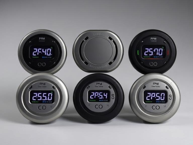
6 Professional Carbon Monoxide Detectors with PPM Displays
Carbon monoxide (CO) is often characterized as the silent killer because it is colorless, odorless, and tasteless. While standard residential alarms are designed…
-
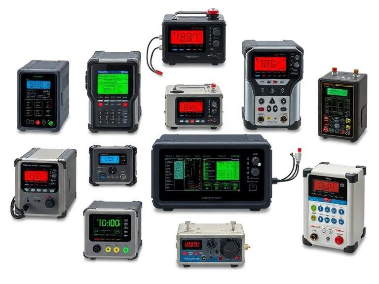
9 Professional Exhaust Gas Analyser Solutions for Industrial Emissions
As industrial regulations tighten globally, the need for precise and reliable emission monitoring has never been more critical. At Sino-Inst, we understand that…
-
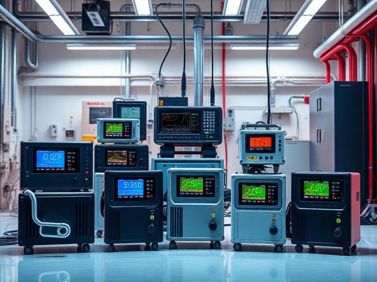
7 Professional Indoor VOC Monitoring Equipment Solutions
Authored by Sino-Inst — A globally recognized manufacturer of industrial instrumentation and process control equipment. From our experience engineering robust sensing technologies, protecting…
-
The Ultimate Guide to Flow Controllers Mass Price in 2026
Authored by Sino-Inst — A leading industrial automation and process control instrument manufacturer specializing in precision flow, pressure, and fluid measurement solutions. In…
-
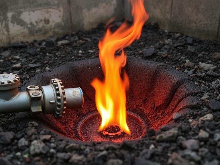
6 Signs of a Natural Gas Leak
Authored by Sino-Inst. We are a professional supplier of industrial process and analytical instruments, including gas detectors, gas analyzers, mass flow controllers, and…
-
The 5 Core Differences Between MFC and MFM
In the realm of process automation, semiconductor manufacturing, and advanced laboratory research, the precise management of gas and liquid flow is not merely…