.png)
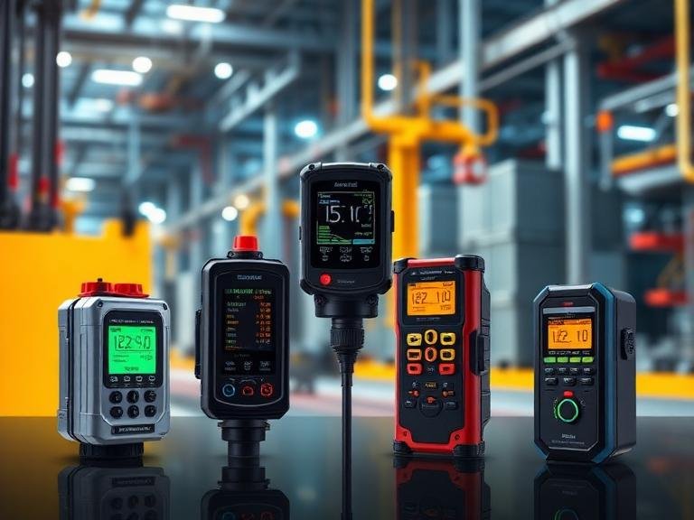
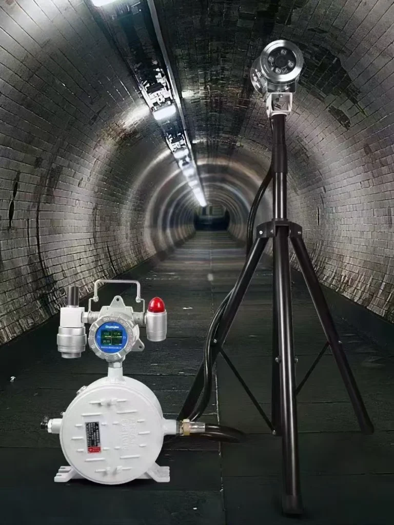
A combustible gas detector is a safety device engineered to identify and quantify the concentration of flammable gases in the ambient atmosphere. Its primary function is to provide an early warning before the concentration of a gas reaches a flammable or explosive level, commonly measured as a percentage of the Lower Explosive Limit (%LEL). Compatible with various control alarms, PLC, DCS and other control systems, it can simultaneously realize on-site alarm and early warning, 4-20mA/RS485 standard signal output, and relay switching output.
These instruments operate on various sensing principles, including catalytic bead (pellistor), infrared (IR), and metal-oxide semiconductor (MOS) technologies, each with distinct advantages for specific applications. The selection and implementation of a combustible gas detector requires a thorough assessment of the operational environment, the specific gas hazards present, and regulatory compliance standards.
Combustible gas detectors are integral to safety protocols in a wide range of industries, from oil and gas refining and chemical manufacturing to wastewater treatment and mining. By continuously monitoring for invisible threats, they serve as a critical line of defense in preventing catastrophic fires and explosions, thereby protecting personnel, assets, and the environment.

The Fundamental Role of a Combustible Gas Detector
To grasp the profound significance of a combustible gas detector, one must first confront the nature of the danger it mitigates. Flammable gases are often colorless and odorless, silent precursors to disaster. They can accumulate in enclosed spaces or spread through open facilities, awaiting only an ignition source to trigger a catastrophic event.
The role of a combustible gas detector is not merely to sense the presence of a gas; it is to act as a vigilant sentinel, quantifying an unseen risk and translating that data into an actionable warning. It provides the critical window of time needed to intervene—to ventilate an area, shut down a process, or evacuate personnel—before conditions escalate to a point of no return.
This function moves beyond simple technological utility; it embodies a fundamental commitment to the preservation of life and the continuity of operations in environments where the potential for combustion is an ever-present reality.
Defining Combustible Gas: More Than Just Fuel
When we speak of a “combustible gas,” the mind often gravitates toward common fuels like natural gas (methane) or propane. While these are certainly primary examples, the category is far broader and more nuanced.
A combustible gas is any substance that, when mixed with an oxidant (usually oxygen in the air) in the right concentration, can ignite and burn. This category encompasses a vast array of chemical compounds, including hydrogen, butane, ethanol, acetylene, and a wide variety of hydrocarbon vapors emanating from solvents, fuels, and industrial chemicals.
The “combustibility” of a gas is not an absolute property but is defined by its chemical structure and its propensity to react with oxygen in an exothermic reaction. Understanding the specific gases present in a particular environment is the foundational step in effective gas detection.
Methane, for instance, is lighter than air and will tend to accumulate near ceilings. Propane, being heavier than air, will pool in low-lying areas like pits or basements. A combustible gas detector must be chosen and placed with this physical behavior in mind, as a device positioned incorrectly is functionally useless, regardless of its technological sophistication.

The Fire Triangle and Explosion Pentagon: A Primer on Combustion Physics
The classic “fire triangle” provides a simple yet powerful model for understanding combustion. It posits that three elements are required for a fire to start and sustain itself: fuel (a combustible gas), an oxidant (oxygen), and heat (an ignition source). Removing any one of these elements breaks the triangle and prevents or extinguishes the fire. A combustible gas detector is fundamentally designed to monitor the “fuel” side of this triangle, alerting us when its concentration reaches a dangerous level.
However, for understanding industrial explosions, a more advanced model, the “explosion pentagon,” is often more instructive. It builds upon the fire triangle by adding two more elements:
- Fuel: The flammable substance.
- Oxidant: Typically oxygen.
- Ignition Source: A spark, flame, or hot surface.
- Dispersion of Gas: The fuel must be adequately mixed with the oxidant.
- Confinement: The gas mixture is in an enclosed or partially enclosed space, allowing pressure to build rapidly upon ignition.
An explosion is essentially a very rapid, self-propagating combustion that creates a high-pressure wave. A combustible gas detector is our primary defense against the formation of this hazardous condition, as it alerts us long before the fuel concentration, mixed with air, finds an ignition source within a confined space. It is a proactive tool designed to dismantle the explosion pentagon before it can be completed.
Lower Explosive Limit (LEL) and Upper Explosive Limit (UEL)
Perhaps the most important concept in the field of combustible gas detection is the Lower Explosive Limit (LEL). The LEL of a gas is the minimum concentration of that gas in the air, expressed as a percentage by volume, that will support combustion. Below the LEL, the mixture is too “lean” to burn; there simply isn’t enough fuel.
Conversely, the Upper Explosive Limit (UEL) is the maximum concentration of a gas in the air that will support combustion. Above the UEL, the mixture is too “rich” to burn; there is not enough oxygen to sustain the reaction. The range between the LEL and UEL is known as the flammable or explosive range.
A combustible gas detector does not typically display the gas concentration as a raw percentage of volume in the air. Instead, it displays it as a percentage of the LEL. For example, methane’s LEL is approximately 5% by volume in air. A detector reading “50% LEL” for methane means that the current concentration is 2.5% methane by volume in the air (50% of the 5% LEL). This %LEL reading is a universal and much more intuitive measure of the immediate hazard. Most safety standards require alarms to be triggered at very low %LEL levels, often with a low alarm at 10% or 20% LEL and a high alarm at 40% or 50% LEL, providing ample time for corrective action.
Step 1: Assessing Your Environment and Identifying Specific Gas Hazards
The process of selecting a combustible gas detector begins not with a product catalog, but with a rigorous and thoughtful examination of the environment it is intended to protect. A detector is a tool, and like any tool, its effectiveness is contingent upon its suitability for the specific task at hand.
To choose the right instrument, one must first become an expert on the potential hazards of the workspace. This requires a systematic approach, moving from a broad understanding of the physical space to a detailed inventory of the chemical substances present. It is an exercise in foresight, demanding that we imagine what could go wrong in order to implement the measures that ensure it does not.
The Character of the Space: Confined vs. Open Areas
The physical layout of a facility is a primary determinant in gas detection strategy. We must first distinguish between confined spaces and open or semi-enclosed areas.
A confined space, as defined by organizations like the U.S. Occupational Safety and Health Administration (OSHA), is an area large enough for an employee to enter but has limited means of entry or exit and is not designed for continuous occupancy.
Examples include storage tanks, process vessels, utility vaults, and pipelines. In these spaces, gases can become trapped and quickly reach explosive concentrations. The behavior of the gas—whether it is lighter or heavier than air—is of paramount importance here. A detector for methane (lighter than air) should be placed high, while one for hydrogen sulfide or propane (heavier than air) must be placed low.
In contrast, open areas like outdoor processing units or loading docks present a different challenge. Natural ventilation can dilute gas leaks, making them harder to detect. However, pockets of gas can still accumulate in areas with poor air circulation, such as corners or behind large equipment.
For these larger areas, “open path” detectors, which use a beam of infrared light to monitor for gas over a long distance (e.g., up to 100 meters or more), can be an effective solution, complementing traditional point detectors. The choice between point detection and open-path detection depends on the geometry of the area and the likely nature of a potential gas release.
Identifying Potential Gas Sources: A Facility Walk-Through
The next logical step is to conduct a meticulous walk-through of the facility with the express purpose of identifying every potential source of a combustible gas leak. This is not a casual stroll; it is a forensic investigation. The focus should be on any point where a system’s integrity could be compromised. This includes:
- Piping and Flanges: Every connection, valve, and flange is a potential leak point.
- Pumps and Compressors: The seals on rotating equipment are common failure points.
- Storage Vessels: Vents, hatches, and pressure relief valves on tanks can release gas.
- Loading/Unloading Stations: The process of connecting and disconnecting hoses is a high-risk activity.
- Process Equipment: Reactors, distillation columns, and other units containing flammable substances.
During this survey, it is vital to consult process flow diagrams (PFDs) and piping and instrumentation diagrams (P&IDs). These documents provide a map of the chemical processes and can reveal the identity and location of combustible materials throughout the plant. Every substance should be cataloged, and its safety data sheet (SDS) reviewed to understand its LEL, UEL, and physical properties.
Environmental Factors: Temperature, Humidity, and Pressure Considerations
A combustible gas detector does not operate in a vacuum. It is part of a larger, dynamic environment, and its performance can be significantly affected by ambient conditions.
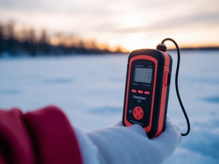
Temperature: Extreme temperatures, both high and low, can impact sensor accuracy and lifespan. Most standard sensors have a defined operating temperature range. For applications like drying ovens, turbine enclosures, or facilities in arctic or desert climates, specialized sensors are required. For example, certain high-temperature combustible gas detection solutions are engineered specifically to function reliably in environments exceeding standard limits.
Humidity and Moisture: High humidity or direct exposure to water can damage the internal electronics of a detector and, in some cases, affect the performance of certain sensor types. Ingress Protection (IP) ratings are a key specification to consider, indicating the device’s resistance to dust and water.
Pressure: While less of a concern for most applications, significant variations in atmospheric pressure can affect the readings of some sensor types.
Presence of Other Substances: The air may contain other non-combustible gases or particulates that could interfere with a sensor. For instance, silicon-containing compounds can “poison” catalytic bead sensors, rendering them ineffective. This possibility must be evaluated during the hazard assessment.
Creating a Gas Hazard Profile for Your Application
The culmination of this assessment is the creation of a comprehensive Gas Hazard Profile. This document, or set of documents, serves as the blueprint for your gas detection strategy. It should be a formal record that details, for each area of the facility, the following information:
| Profile Component | Description | Example |
| Area/Location | The specific part of the facility being assessed. | Pump Alley #3, East Wing |
| Potential Gases | A list of all combustible gases that could be present. | Methane (CH4), Hydrogen (H2) |
| Gas Properties | Key data for each gas (LEL, UEL, vapor density). | Methane: LEL=5%, Vapor Density=0.55 (Lighter than air) |
| Potential Sources | Specific equipment or points where a leak could occur. | Compressor seals, pipeline flanges, valve stems |
| Environmental Conditions | Typical and extreme temperature, humidity, etc. | Ambient Temp: -10°C to 30°C; High humidity |
| Space Classification | Confined space, open area, ventilation characteristics. | Semi-enclosed, moderate natural ventilation |
| Ignition Sources | A list of potential sources of ignition in the area. | Electrical motors, welding (hot work), static discharge |
This profile is not a static document. It should be reviewed and updated whenever a process is changed, new chemicals are introduced, or equipment is modified. It is the foundational intellectual work upon which a robust and reliable safety system is built.
Step 2: Exploring Core Sensor Technologies
Once we have a clear understanding of the hazards within our environment, the next intellectual step is to turn our attention to the technology designed to detect them. The heart of any combustible gas detector is its sensor. This is the component that directly interacts with the atmosphere and produces a signal in response to the presence of a target gas.
There is no single “best” sensor technology; rather, there are several distinct approaches, each with its own underlying physical or chemical principle, and each with a unique profile of strengths and weaknesses. Choosing the correct sensor is a matter of aligning the technology’s capabilities with the specific demands of the application as defined in our Gas Hazard Profile. A deep appreciation for how these sensors work is not merely an academic exercise; it is essential for making an informed and responsible decision.
Catalytic Bead (Pellistor) Sensors: The Workhorse of the Industry
The catalytic bead sensor, often called a pellistor, is one of the most widely used and time-tested technologies for detecting combustible gases. Its operation is elegantly simple and rooted in basic chemistry.
The sensor consists of two small ceramic beads, often no larger than the head of a pin. Each bead has a platinum wire coil embedded within it, which serves both as a heater and a temperature sensor.
One bead, the “active” bead, is coated with a catalyst, typically a precious metal like palladium or platinum. The other bead, the “reference” bead, is inert, treated to prevent it from reacting with gas.
In operation, a current is passed through both coils, heating the beads to a high temperature (typically 400-500°C). When a combustible gas comes into contact with the hot active bead, the catalyst promotes its oxidation (burning). This exothermic reaction generates additional heat, causing the temperature of the active bead to rise. This temperature increase, in turn, causes a change in the electrical resistance of the platinum wire coil inside it.
The active and reference beads are arranged as two arms of a Wheatstone bridge circuit. The reference bead’s temperature and resistance remain stable, compensating for any changes in ambient temperature, humidity, or pressure that would affect both beads equally.
However, the heat produced by the gas oxidation unbalances the bridge. This imbalance creates a voltage signal that is directly proportional to the concentration of the combustible gas. It is a robust, relatively inexpensive, and reliable method that can detect a broad range of combustible gases.
Infrared (IR) Sensors: Precision Through Light Absorption
Infrared (IR) sensor technology operates on a completely different principle: the absorption of light. Many hydrocarbon gases (which constitute a large portion of combustible gases) have a unique property: they absorb infrared radiation at specific wavelengths. An IR sensor exploits this characteristic to detect and measure the gas.
The sensor contains an infrared light source, a sample chamber through which the ambient air passes, and an IR detector. The light source emits a beam of IR radiation that travels through the chamber to the detector.
The detector is fitted with optical filters that allow it to measure the intensity of light at two different wavelengths: a “measuring” wavelength that is known to be absorbed by the target gas (e.g., around 3.4 micrometers for most hydrocarbons), and a “reference” wavelength that is not absorbed by the gas.
In clean air, the detector receives the maximum intensity of light at both wavelengths. When a combustible hydrocarbon gas enters the chamber, it absorbs some of the light at the measuring wavelength, reducing the intensity of the beam that reaches the detector. The reference wavelength remains unaffected. The sensor’s electronics compare the intensity of the two wavelengths. The difference between them is a precise measure of the concentration of gas present in the chamber.
This method offers several key advantages: it is immune to sensor poisoning, it can operate in low-oxygen or anaerobic environments, and it fails to a safe state (a loss of signal is registered as a fault, unlike a poisoned catalytic sensor which might simply stop responding).
Metal-Oxide Semiconductor (MOS) Sensors: A Sensitive Alternative
Metal-Oxide Semiconductor (MOS) sensors represent a third major category. These sensors are based on a heated metal oxide layer, typically tin dioxide (SnO2), deposited on a ceramic substrate. In clean air, oxygen from the atmosphere adsorbs onto the surface of the metal oxide, trapping electrons and creating a high-resistance state.
When a combustible gas (which acts as a reducing agent) is introduced, it reacts with the adsorbed oxygen on the sensor surface. This reaction releases the trapped electrons back into the metal oxide, causing a significant drop in the sensor’s electrical resistance. This change in resistance is measured and correlated to the gas concentration.
MOS sensors are known for their very high sensitivity, allowing them to detect low parts-per-million (ppm) levels of gas, sometimes even below the concentrations needed for LEL detection. They also have a long operational life.
However, they can be less specific than other types, sometimes responding to a broad range of reducing gases, including non-combustible ones. They can also be affected by humidity and require a stable power supply and warm-up time to provide a consistent reading. Their high sensitivity makes them valuable in certain applications, particularly for low-level leak detection.
A Comparative Analysis: Choosing the Right Sensor for the Job
The selection of a sensor technology is a critical decision that directly impacts the reliability and safety of the entire gas detection system. It is a choice that must be made with a clear understanding of the application’s unique requirements, weighing the pros and cons of each option.
| Feature | Catalytic Bead (Pellistor) | Infrared (IR) | Metal-Oxide Semiconductor (MOS) |
| Principle | Catalytic Oxidation | NDIR Light Absorption | Change in Semiconductor Resistance |
| Gases Detected | Broad range of combustibles | Primarily hydrocarbons | Broad range of reducing gases |
| Oxygen Required? | Yes | No | Yes |
| Immunity to Poisoning | No (vulnerable to silicones, sulfur) | Yes | Moderate (can be affected by some chemicals) |
| Response Time | Fast (T90 < 10 seconds) | Fast (T90 < 10 seconds) | Moderate (can be slower) |
| Lifespan | 3-5 years (typical) | 5-10+ years | 5-10+ years |
| Cost | Low to Moderate | High | Moderate |
| Failsafe Operation | No (can fail to a zero reading) | Yes (beam block triggers fault) | Partial (can drift over time) |
| Best For | General-purpose, cost-sensitive | Low-oxygen, poison-risk areas | Low-level leak detection, high sensitivity |
The Nuances of Sensor Poisoning and Inhibition
One of the most critical considerations, especially when evaluating catalytic bead sensors, is the concept of sensor poisoning and inhibition. These phenomena can silently disable a detector, creating a false sense of security.
Sensor Poisoning is a permanent and irreversible loss of sensitivity. It occurs when certain chemicals react with the catalyst on the active bead, destroying its ability to oxidize gas.
The most common culprits are silicon-containing compounds (found in some lubricants, sealants, and cleaning agents), lead compounds, and high concentrations of sulfur compounds. A poisoned sensor will not respond to gas, yet it may appear to be functioning normally, outputting a zero reading. This is a particularly dangerous failure mode.
Inhibition is a temporary loss of sensitivity. It is caused by exposure to certain chemicals, most notably halogenated hydrocarbons (like refrigerants or cleaning solvents). An inhibitor can temporarily block the active sites on the catalyst, but the sensor may recover its sensitivity once it is returned to clean air for a period.
The risk of poisoning or inhibition is a powerful argument for choosing IR sensor technology in environments where these interfering substances are known to be present. If a catalytic sensor is used, it underscores the absolute necessity of a rigorous bump testing and calibration schedule to verify that the sensor is still responsive.
Step 3: Differentiating Between Fixed and Portable Gas Detection Systems
Having explored the internal workings of the sensors themselves, our perspective must now broaden to consider the physical form in which this technology is deployed. The choice is not just what technology to use, but how and where it should be implemented. The world of combustible gas detection is generally divided into two major categories: fixed systems and portable devices.
These are not competing options but rather complementary tools that serve different, though sometimes overlapping, purposes. The decision to use one, the other, or a combination of both is driven by a strategic assessment of the operational needs, the nature of the work being performed, and the overall safety philosophy of the organization.
Fixed Gas Detection: The Silent Sentinels for Continuous Monitoring
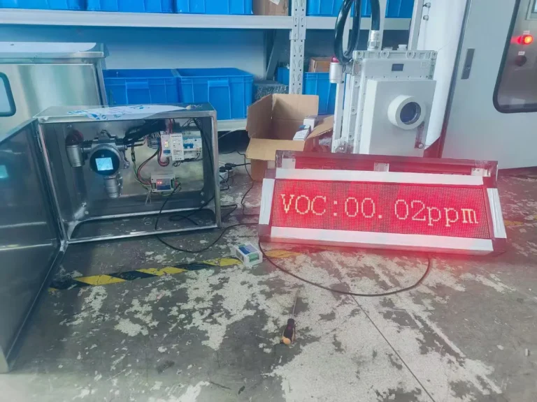
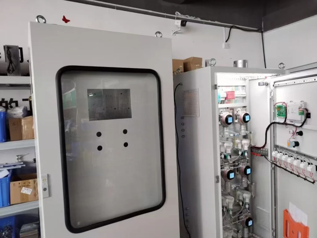
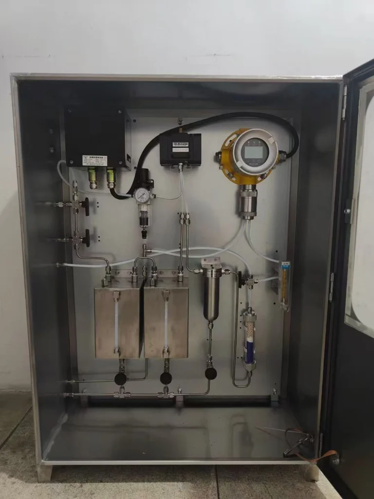
A fixed gas detection system is, as the name implies, a permanent installation. It consists of one or more detector heads mounted in specific locations, wired back to a central controller panel. This system is designed to be a silent, ever-watchful sentinel, providing continuous, 24/7 monitoring of a specific area, process, or piece of equipment.
The purpose of a fixed system is to protect a location. It guards against leaks from pipes, vessels, and compressors, providing an early warning of a developing hazard long before personnel may be present. The controller panel typically displays the gas readings from all connected detectors and is programmed to initiate automatic actions when a pre-set alarm level is reached. These actions can range from activating audible and visual alarms (horns and strobes) to triggering emergency ventilation systems, initiating process shutdowns, or closing emergency isolation valves.
The placement of fixed detectors is a science in itself, guided by the Gas Hazard Profile we previously developed. For lighter-than-air gases like methane or hydrogen, detectors are mounted high, near ceilings or above potential leak sources. For heavier-than-air gases like propane or butane, they are mounted low to the ground. In large, open areas, a grid of point detectors or long-range open-path detectors might be used to provide comprehensive coverage. Fixed systems are the backbone of plant safety, forming the primary layer of defense for the facility itself.


Portable Gas Detectors: Personal Protection on the Move
In contrast to the location-centric nature of fixed systems, a portable gas detector is designed to protect a person. It is a small, typically battery-powered device worn by an individual, usually on their clothing within their “breathing zone.” Its function is to provide an immediate, personal warning if the wearer enters an area where a hazardous gas concentration is present.
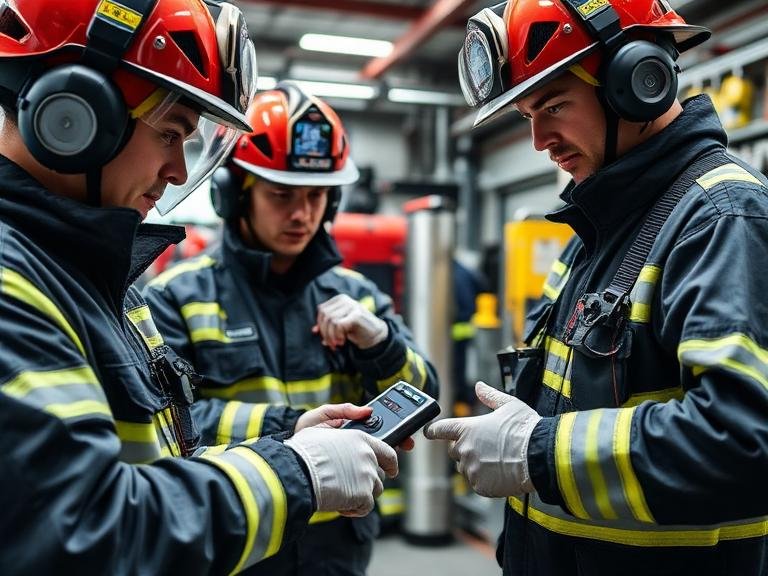
Portable detectors are indispensable for personnel who move throughout a facility, such as maintenance technicians, operators taking readings, and emergency responders. They are the essential tool for entry into confined spaces. Before a worker enters a tank or vessel, a portable detector (often mounted on a probe) is used to test the atmosphere inside to ensure it is safe. The worker then wears a personal monitor continuously while inside the space.
These devices are typically multi-gas monitors, capable of detecting not only combustible gases (%LEL) but also oxygen deficiency and one or more toxic gases (like carbon monoxide or hydrogen sulfide). They are equipped with loud audible alarms, bright flashing lights, and a vibrating alarm to ensure the user is alerted to danger even in noisy, high-activity environments. A portable detector is a personal lifeline, a piece of personal protective equipment (PPE) as vital as a hard hat or safety glasses.
A Hybrid Approach: Integrating Fixed and Portable Systems for Comprehensive Safety
The most robust safety strategies do not treat the choice between fixed and portable systems as an either/or proposition. Instead, they employ a hybrid approach, leveraging the strengths of both to create a multi-layered defense.

Consider a scenario: a pump in a processing unit begins to leak a flammable liquid, creating a combustible vapor cloud.
- Layer 1 (Fixed Detection): A fixed combustible gas detector located near the pump senses the vapor. At 10% LEL, it triggers a local alarm horn and a yellow flashing light, while also sending an alert to the main control room. This is the first indication of a problem.
- Layer 2 (Personnel Response): An operator is dispatched to investigate the alarm. As they approach the area, their personal portable gas detector begins to alarm, confirming the presence of a gas cloud and warning them not to get closer without proper respiratory protection.
- Layer 3 (Escalation): As the leak worsens, the concentration rises. The fixed detector reaches its high alarm setpoint of 40% LEL. This automatically triggers a plant-wide evacuation alarm and initiates an emergency shutdown of the process unit.
In this example, the fixed system provided the initial, plant-level protection, while the portable device provided the crucial, person-specific protection for the responding operator. Together, they form a cohesive system that manages the incident safely and effectively. This integrated philosophy recognizes that you must protect both your assets and your people.
Choosing Between Fixed and Portable: A Decision Framework
The determination of where to use fixed systems, where to mandate portable detectors, and where to use both, should be a deliberate process based on risk assessment.
| Consideration | Favors Fixed System | Favors Portable Detector |
| Primary Goal | Protect a specific area or asset 24/7. | Protect a mobile individual. |
| Personnel Presence | Area is unmanned or intermittently occupied. | Area is frequently accessed by personnel. |
| Hazard Type | Predictable, known leak sources. | Unpredictable or unknown hazard locations. |
| Task | Continuous process monitoring. | Confined space entry, maintenance, spot checks. |
| Response | Automated shutdown, plant-wide alarms. | Personal alert, immediate self-evacuation. |
| Cost Structure | Higher initial capital investment. | Lower initial cost per unit, higher ongoing management. |
Ultimately, a facility with any significant combustible gas risk will almost certainly require a combination of both. Fixed systems stand guard over the known risks, while portable detectors protect people as they move through the dynamic operational landscape.
Step 4: Navigating Calibration, Maintenance, and Regulatory Compliance
The acquisition and installation of a combustible gas detector, whether fixed or portable, is not the end of the safety journey; it is merely the beginning. A detector is not a “fit and forget” device. It is a precision instrument whose reliability is entirely dependent on a disciplined program of ongoing care and verification. Without proper maintenance and regular calibration, a detector can become a source of dangerous false confidence.
Furthermore, these devices operate within a strict framework of national and international regulations and standards. Adhering to these standards is not just a matter of best practice; it is a legal and ethical obligation. This phase of the process requires diligence, record-keeping, and an unwavering commitment to procedural correctness.
The Imperative of Calibration: Ensuring Accuracy and Reliability
Calibration is the process of verifying and adjusting a detector’s response to a known concentration of a target gas. It is the only way to be certain that the device’s reading is accurate. Over time, all sensors can experience “drift” in their output due to aging components, environmental stresses, or low-level exposure to contaminants. Calibration corrects for this drift, realigning the sensor’s response with its expected output.
The process involves exposing the sensor to a certified calibration gas—a carefully prepared mixture containing a known concentration of the target gas (e.g., 50% LEL methane). The technician then adjusts the instrument’s internal settings so that its reading matches the concentration of the gas being applied. This ensures that a reading of “50% LEL” on the display truly corresponds to a 50% LEL concentration in the atmosphere.
How often should a device be calibrated? Manufacturers provide recommendations, but the required frequency is ultimately determined by company policy, regulatory requirements, and the specific application. In critical-risk environments or where sensors are exposed to harsh conditions, calibration might be required as often as every 30 days. In less demanding applications, a 90- or 180-day interval might be acceptable. Regardless of the interval, a regular, documented calibration schedule is non-negotiable for any credible safety program.
Bump Testing vs. Full Calibration: What’s the Difference?
There is often confusion between a “bump test” and a “full calibration.” The two procedures serve different but equally important purposes.
A Bump Test (or functional check) is a qualitative check to ensure that the sensor is responding to gas and that the alarms are functioning. The user briefly exposes the detector to a concentration of gas that is high enough to trigger the alarms. If the sensor responds and the audible, visual, and vibrating alarms activate, the test is successful. The goal is not to check for accuracy, but simply to confirm that the device is alive and capable of alarming. Many organizations require users to bump test portable detectors at the start of every shift. It is a quick, go/no-go safety check.
A Full Calibration, as described previously, is a quantitative procedure. It involves adjusting the instrument to match a known standard. It is a much more involved process that corrects for sensor drift and ensures the instrument’s accuracy.
Think of it this way: a bump test asks the question, “Is the detector working?” A full calibration asks, “Is the detector working correctly?” A comprehensive safety program requires both: frequent bump tests to ensure functionality and periodic full calibrations to ensure accuracy.
Developing a Maintenance Schedule: Best Practices for Longevity
Beyond calibration, a combustible gas detector requires routine maintenance to ensure its long-term reliability. A formal maintenance schedule should be developed and rigorously followed. Key activities include:
- Visual Inspection: Regularly check the device for physical damage, cracks in the housing, or blockages over the sensor opening.
- Filter Replacement: Most detectors have a filter to protect the sensor from dust, dirt, and moisture. These filters must be inspected and replaced regularly, as a clogged filter can prevent gas from reaching the sensor.
- Battery Care (for portables): Ensure batteries are fully charged before use. Follow the manufacturer’s guidelines for battery replacement to avoid unexpected device failure during a shift.
- Cleaning: Keep the instrument’s housing clean according to the manufacturer’s instructions. Avoid using solvents or harsh cleaning agents that could damage the device or its sensors.
- Record Keeping: Meticulous records are a cornerstone of a good maintenance program. Every calibration, bump test, filter change, and repair should be logged for each individual detector. This data trail is essential for tracking performance, identifying trends (e.g., a sensor that requires frequent recalibration), and providing evidence of due diligence during a safety audit.
Understanding Certifications and Standards (ATEX, IECEx, UL)
Combustible gas detectors are designed to be used in hazardous locations where the risk of an explosion is present. Therefore, the detectors themselves must be designed so that they cannot become an ignition source. This is achieved through various protection methods (e.g., “intrinsically safe” or “explosion-proof” design).
To ensure these devices are safe for their intended use, they are tested and certified by third-party agencies according to specific regional and international standards. Understanding these certifications is vital when selecting a detector.
- ATEX Directives: This is the legal framework for equipment used in potentially explosive atmospheres within the European Union. Products certified under ATEX will bear the “Ex” symbol and markings that indicate the specific zones and environments for which they are approved.
- IECEx (International Electrotechnical Commission System for Certification to Standards Relating to Equipment for Use in Explosive Atmospheres): This is an international certification system that aims to harmonize standards worldwide. An IECEx certificate can simplify the process of achieving national certification in member countries.
- UL (Underwriters Laboratories) / CSA (Canadian Standards Association): These are the primary standards bodies for North America. They provide classifications for equipment used in hazardous locations based on the Class/Division system (e.g., Class I, Division 1).
When purchasing a combustible gas detector, you must ensure that its certifications are appropriate for the geographical location and the specific hazardous zone classification of the area where it will be installed. Using a non-certified or improperly certified device in a hazardous area is a serious safety violation. These standards, as detailed in resources like the MSA Gas Detection Handbook, provide a common language and a benchmark for safety and performance.
Step 5: Selecting and Implementing Your Combustible Gas Detector System
The final step in our journey is the synthesis of all previous analysis into a concrete plan of action. We have assessed our environment, understood the technology, differentiated between system types, and acknowledged our maintenance obligations. Now, we must make the final selection and implement the system in a way that maximizes its effectiveness. This stage moves from the theoretical to the practical, involving decisions about alarm thresholds, data management, physical installation, and, most importantly, the human element. A perfectly specified and calibrated detector is of little value if the response to its alarm is slow, confused, or incorrect.
Defining Alarm Setpoints and Response Protocols
An alarm is not just a noise; it is a call to action. Before a single detector is installed, a clear and unambiguous policy must be established regarding alarm setpoints and the required response for each alarm level. Most combustible gas detection systems use a two-stage alarm system:
- Low Alarm: This is the initial warning. A common setpoint is 10% or 20% LEL. The response to a low alarm is typically to investigate the source of the gas while exercising caution. It is an “alert” condition.
- High Alarm: This indicates a more serious situation. A common setpoint is 40% or 50% LEL. The response to a high alarm is typically immediate evacuation of the area and initiation of emergency procedures. It is a “danger” condition.
These setpoints should be standardized across a facility to avoid confusion. The response protocols must be documented, and personnel must be thoroughly trained on them. What should an operator do when they hear a low alarm? Who should they notify? What actions should they take if their portable detector alarms? What are the evacuation routes in case of a high alarm? These questions must have clear, pre-determined answers. The response plan is as critical as the hardware itself.
Data Logging and System Integration: Beyond the Alarm
Modern gas detection systems are capable of much more than simply triggering an alarm. Most fixed system controllers and many portable detectors have data logging capabilities. This feature records gas concentrations over time, along with alarm events. This data is an invaluable resource for safety management. Analyzing this data can help to:
- Identify small, persistent leaks that may not be large enough to trigger an alarm but indicate a developing problem.
- Recognize patterns, such as gas peaks that occur during a specific process or time of day.
- Provide a detailed record of an incident for subsequent investigation.
- Demonstrate regulatory compliance during an audit.
Furthermore, fixed gas detection systems are rarely standalone. They are often integrated into a larger plant control and safety system, such as a Distributed Control System (DCS) or a Safety Instrumented System (SIS). This integration allows gas alarm information to be displayed directly on operator consoles and enables the gas detection system to automatically trigger complex safety functions managed by the SIS. A well-integrated system provides a holistic view of plant safety and enables a more coordinated and powerful response to hazardous events.
Installation Best Practices: Sensor Placement and Wiring
The physical installation of the system must be performed with the same level of care as its selection. Poor installation can undermine the effectiveness of even the most advanced detector.
- Sensor Placement: This is the most critical aspect of installation. As previously discussed, the location must be chosen based on the vapor density of the target gas and the location of potential leak sources. The sensor must be positioned where a leak is most likely to be detected quickly. Avoid placing sensors in “dead air” spots where ventilation is poor, or directly in high-velocity air streams that might dilute a gas sample. The manufacturer’s instructions provide essential guidance on proper orientation and mounting.
- Accessibility: The sensor must be installed in a location where it is safely accessible for future calibration and maintenance. Placing a sensor 50 feet in the air with no platform for access is a common mistake that leads to neglected maintenance.
- Wiring (for fixed systems): All wiring must be done in accordance with the National Electrical Code (NEC) or other applicable local codes. Wiring must be appropriate for the hazardous area classification. Proper shielding and grounding are essential to prevent electrical interference (noise) that could cause false readings or alarms.
Training Personnel: The Human Element in Gas Safety
Ultimately, technology alone cannot guarantee safety. The human element is the final and most important link in the chain. All personnel who work in or near areas with combustible gas hazards must receive comprehensive training. This training should cover:
- The nature of the specific gas hazards in their work area.
- How to interpret the readings on both fixed and portable detectors.
- The meaning of the different alarms and the specific actions they must take for each.
- How to properly use and care for their personal portable gas detectors, including how to perform a bump test.
- Emergency evacuation procedures.
Training should not be a one-time event. Refresher training should be conducted regularly to ensure that knowledge is retained and that personnel are aware of any changes in procedures or equipment. A well-trained workforce, equipped with reliable and properly maintained gas detection instruments, forms the most resilient defense against the invisible threat of combustible gases. This fusion of technology and human competence is the true goal of any industrial safety program.
FAQ
Related Products
The journey to understanding and implementing a combustible gas detection system is a profound exercise in risk mitigation and safety stewardship.
From combustible gas sensor selection to deployment and installation, maintenance, and calibration, we face a complex set of trade-offs.
A combustible gas detector is a tool whose ultimate value is realized through the training, preparation, and vigilance of the people who work alongside it. It is a partnership between human expertise and technological capability, a synthesis that transforms a simple instrument into a cornerstone of a resilient and enduring safety culture.
Sino-Inst’s combustible gas detectors have been widely used in various countries, including the United States, Germany, Italy, Chile, and Indonesia. If you also need to build a gas detection system, please feel free to contact our sales engineers for technical support!
More Resources
-
The Expert Guide to OSHA Requirements for Confined Space Air Monitoring
Navigating the complex landscape of industrial safety is a critical responsibility for any plant manager, safety officer, or environmental health professional. Among the…
-
Does Chlorine Reduce pH in Pool?Owner Needs to Know in 2026
Does chlorine reduce pH? This issue remains at the core of water quality management when maintaining a clear and transparent swimming pool. Many…
-
7 Best portable carbon monoxide detector for International travel
Carbon monoxide (CO) is a silent, invisible, and lethal threat that claims thousands of lives globally every year. For the international traveler, the…
-
7 Best Sensor Gas Detector Systems for Industrial Safety in 2026
By Sino-Inst — Industrial Instrumentation Experts In modern industrial environments, the margin for error when managing hazardous gases is absolutely zero. Whether you…
-
What Best Gas Detectors Do Fire Departments Use?
Introduction to Fire Service Gas Detection When lives are on the line and seconds count, first responders cannot rely on guesswork. Identifying hazardous…
-
Top 10 Portable Carbon Monoxide Detector for Ice Fishing
Authored by Sino-Inst. We are a leading manufacturer and supplier of professional gas detection, flow measurement, and industrial instrumentation solutions. With decades of…