.png)
In industrial process control, achieving precise measurement and regulation of gas and liquid flows is an absolute necessity. Whether you are engineering a semiconductor fabrication facility, managing a bioreactor, or developing advanced analytical instrumentation, you need components that deliver flawless accuracy. To achieve this, engineers rely heavily on the mass flow controller (MFC). Understanding the mass flow controller working principle is fundamental for process engineers, procurement specialists, and system integrators who need to ensure optimal fluid dynamic control in their applications.
From our experience in the analytical and industrial instrumentation sector, many operational inefficiencies stem from a basic misunderstanding of how these devices actually measure and govern flow. Unlike volumetric flow meters, which are highly susceptible to fluctuations in temperature and pressure, an MFC measures the actual mass of the fluid. This guide provides a deep, authoritative exploration of the mass flow controller working principle, detailing its core mechanisms, internal components, and practical applications in modern industry.
Table of Contents
- 1. What is a Mass Flow Controller?
- 2. The Mass Flow Controller Working Principle Explained
- 3. Key Components Driving the Mass Flow Controller Working Principle
- 4. Expert Solutions from Sino-Inst
- 5. Industrial Applications of MFCs
- 6. Summary Table: Mass Flow Controller Comparison
- 7. Frequently Asked Questions (FAQs)
- 8. Industry References
1. What is a Mass Flow Controller?
A mass flow controller is a self-contained device designed to accurately measure and control the flow of gases or liquids based on mass, rather than volume. Because gases are highly compressible, measuring their volume is often unreliable unless strict temperature and pressure compensations are applied. By utilizing the mass flow controller working principle, these devices bypass the need for external temperature or pressure correction, directly calculating the molecular mass passing through the flow channel.
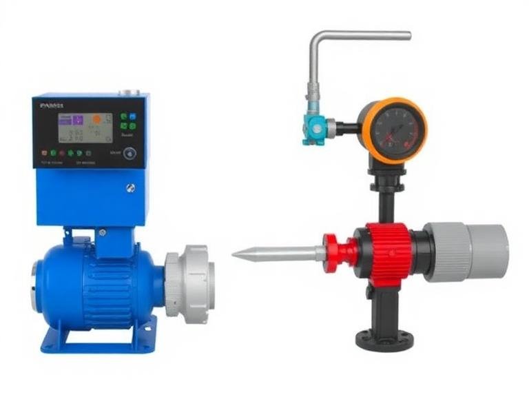
An MFC is typically composed of three primary functional blocks: a flow sensor, a proportional control valve, and an electronic printed circuit board (PCB) acting as the brain. The user inputs a desired setpoint (the target flow rate) via an analog signal or digital interface. The device then continuously measures the actual flow rate, compares it to the setpoint, and automatically adjusts the control valve to eliminate any error. We recommend utilizing MFCs in any application where chemical stoichiometry, precise mixing, or exact dosing is required.
2. The Mass Flow Controller Working Principle Explained
To grasp the true efficiency of these instruments, one must look closely at the physics governing them. The mass flow controller working principle can generally be categorized into two primary technological approaches: thermal dispersion and the Coriolis effect. Both methods provide direct mass flow measurement but apply completely different physical laws to achieve it.
2.1 Thermal Dispersion Mass Flow Controllers
The vast majority of gas mass flow controllers operate on the thermal dispersion principle. The thermal mass flow controller working principle is based on the specific heat capacity of the gas being measured. Inside the device, the main flow path is divided into two sections: a large bypass tube and a small capillary sensor tube. A fixed proportion of the total gas flow is directed through the sensor tube.
The sensor tube is wrapped with two resistance temperature detector (RTD) wire coils. An electric current passes through these coils, heating the tube. When there is zero flow, the heat is distributed evenly, and both RTD coils read the exact same temperature. However, when gas flows through the sensor tube, it absorbs heat from the first (upstream) coil and carries it to the second (downstream) coil. This creates a temperature differential (Delta T) between the two coils.
According to the thermal mass flow controller working principle, this temperature differential is directly proportional to the mass flow rate of the gas, provided the specific heat capacity of the gas remains constant. The electronic circuitry measures this Delta T, calculates the mass flow rate of the fraction passing through the sensor, and scales it up to determine the total mass flow through the entire device. Once the flow is calculated, the control circuitry modulates the proportional valve to match the programmed setpoint.
2.2 Coriolis Mass Flow Controllers
While thermal MFCs dominate gas applications, the Coriolis mass flow controller working principle is frequently utilized for high-precision liquid control and variable gas mixtures. A Coriolis MFC contains a vibrating tube through which the fluid flows. As the fluid moves through this oscillating tube, it induces a slight twisting motion due to the Coriolis inertia effect. Sensors measure the phase shift in the tube’s vibration, which is directly proportional to the mass flow rate of the fluid.
From our experience, while Coriolis controllers offer exceptional accuracy and are immune to fluid heat capacity variations, they represent a larger capital investment compared to thermal units. For most standard industrial gas applications, the thermal mass flow controller working principle remains the most cost-effective and reliable choice.
3. Key Components Driving the Mass Flow Controller Working Principle
To fully appreciate the mass flow controller working principle, it is helpful to break down the internal architecture of the device. The seamless interaction between these components dictates the instrument’s accuracy, response time, and longevity.
- The Sensor Assembly: As described in the thermal mass flow controller working principle, this is the capillary tube wound with precision heating and sensing elements. It acts as the primary measuring instrument.
- The Flow Bypass: Because the sensor tube is incredibly narrow (often just a fraction of a millimeter in diameter), it cannot handle the entire flow volume. The bypass acts as a laminar flow element, ensuring a perfectly proportional split of the gas. The ratio of gas going through the sensor versus the bypass must remain strictly linear across the entire flow range for the mass flow controller working principle to remain valid.
- The Proportional Control Valve: Typically a solenoid or piezoelectric valve, this component physically throttles the gas. Based on signals from the PCB, the valve opens or closes by microscopic increments to maintain the exact setpoint.
- The PCB and Firmware: The electronic brain interprets the sensor signals, linearizes the data based on the specific gas calibration curve, and drives the control loop. Advanced firmware allows modern MFCs to achieve response times of less than a second.
4. Expert Solutions from Sino-Inst
Procuring reliable instrumentation requires partnering with a manufacturer that deeply understands the nuances of the mass flow controller working principle. Sino-Inst is a professional supplier of industrial process and analytical instruments, including gas detectors, gas analyzers, dust detectors, mass flow controllers, and dust monitors. We can help you obtain reliable measurement and analysis solutions while saving procurement costs. Customized products and OEM services are available, ensuring we will be your most trusted partner in process optimization.
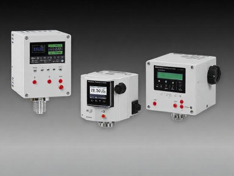
We recommend the following specialized instruments from our portfolio, each engineered to leverage the precise mass flow controller working principle for specific industrial needs:
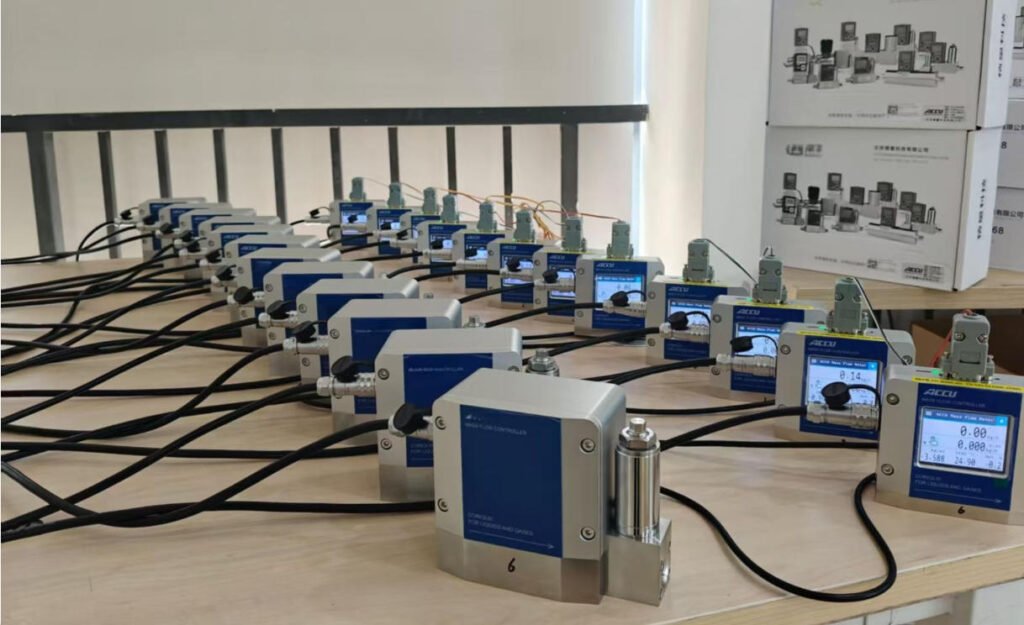
- SI-10FA Analog Mass Flow Controller/Meter: A robust, industry-standard device utilizing the thermal mass flow controller working principle. It provides reliable analog signals (0-5V, 4-20mA) ideal for legacy control systems requiring steady, drift-free performance.
- SI-10FD Digital Mass Flow Controller/Meter: For modern, data-driven facilities, this unit offers digital communication protocols (RS485, Modbus). It allows for multi-gas calibration and higher precision tuning, perfectly demonstrating the evolution of the mass flow controller working principle in the digital age.
- SI-20FDR Gas Mass Flow Controller | High Accuracy – Low Differential Pressure: Engineered for applications with strict pressure drop limitations. This model utilizes advanced bypass technology to maintain the integrity of the mass flow controller working principle even when supply pressures are exceptionally low.
- SI-10HT High Temperature Mass Flow Controller-Meter: Standard thermal sensors can degrade in extreme heat. The SI-10HT features specialized materials and remote electronics, ensuring accurate mass flow measurement in high-temperature environments where standard units would fail.
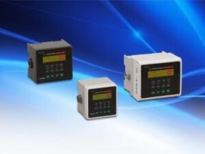
- 10FA-XS Flow Display Controller: To complement our MFCs, this dedicated display unit provides operators with real-time visualization of flow rates, totalization, and setpoint adjustment without requiring a complex PLC integration.
5. Industrial Applications of MFCs
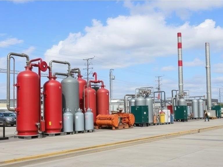
The reliance on the mass flow controller working principle spans multiple high-tech industries. In semiconductor manufacturing, MFCs are used to precisely dose reactant gases into chemical vapor deposition (CVD) chambers. A deviation of even a few standard cubic centimeters per minute (sccm) can ruin a batch of silicon wafers. Therefore, the rapid response time and accuracy inherent to the mass flow controller working principle are indispensable.
In the biopharmaceutical sector, mass flow controllers manage the sparging of oxygen, nitrogen, and carbon dioxide into bioreactors. By relying on the thermal mass flow controller working principle, scientists can maintain exact dissolved oxygen levels necessary for optimal cell culture growth, independent of atmospheric pressure changes. Furthermore, in burner control and flame coating applications, MFCs guarantee the perfect stoichiometric ratio of fuel to oxidizer, optimizing energy efficiency and reducing hazardous emissions.
6. Summary Table: Mass Flow Controller Comparison
To aid in your selection process, the following table summarizes the different products offered by Sino-Inst and how they align with specific operational requirements based on the mass flow controller working principle.
| Sino-Inst Model | Core Technology | Signal Interface | Best Suited Application |
|---|---|---|---|
| SI-10FA Analog MFC | Thermal Dispersion | Analog (4-20mA / 0-5V) | Standard industrial integration, cost-effective OEM builds. |
| SI-10FD Digital MFC | Thermal Dispersion | Digital (RS485, Modbus) | Automated laboratories, multi-gas capable systems. |
| SI-20FDR Low DP MFC | Advanced Thermal | Digital / Analog | Systems with low supply pressure, vacuum applications. |
| SI-10HT High Temp MFC | Thermal Dispersion | Digital / Analog | Heated gas lines, metallurgical processes, exhaust analysis. |
| 10FA-XS Flow Display | N/A (Controller/Display) | Compatible with SI series | Local readout and manual setpoint adjustment for operators. |
7. Frequently Asked Questions (FAQs)
A variable area flow meter measures volumetric flow. Because gas expands and contracts with changes in temperature and pressure, volumetric measurements are highly inaccurate unless manually calculated to standard conditions. The mass flow controller working principle directly measures molecular mass, making it immune to typical temperature and pressure fluctuations, resulting in vastly superior accuracy.
Yes, but the mass flow controller working principle relies on the specific heat capacity of the gas. If you calibrate an MFC for Nitrogen but run Argon through it, the reading will be incorrect because Argon absorbs heat differently. Modern digital MFCs, like the SI-10FD, store multiple gas calibration curves in their memory, allowing users to switch gas types without physically recalibrating the device.
From our experience, the most common cause of accuracy degradation is sensor contamination. If dirty, oily, or particulate-laden gas enters the capillary tube, it alters the heat transfer properties required by the thermal mass flow controller working principle. We strongly recommend installing inline particulate filters upstream of your MFC to protect the delicate internal sensors.
We recommend an annual recalibration for standard industrial environments to ensure the mass flow controller working principle is functioning within the stated accuracy specifications. In highly critical applications, such as pharmaceutical manufacturing or aerospace testing, bi-annual calibration may be required by industry regulations.
8. Industry References
To further understand the physics and industry standards governing the mass flow controller working principle, we recommend consulting the following authoritative sources:
- National Institute of Standards and Technology (NIST) – Provides definitive guidelines on fluid mechanics, mass flow metrology, and traceability standards for gas measurement.
- International Society of Automation (ISA) – Offers comprehensive technical resources on process control instrumentation and proportional valve mechanics.
- International Organization for Standardization (ISO) – Specifically ISO 1179 and related standards governing pneumatic fluid power and connections for industrial mass flow devices.