.png)
In modern industrial processes, precision is not a luxury; it is a fundamental requirement. Whether managing gas distribution in semiconductor manufacturing, controlling bioreactor environments, or ensuring exact stoichiometric ratios in chemical synthesis, fluid control dictates the success of the entire operation. Engineers and procurement specialists frequently ask us about the fundamental mechanics of these devices, specifically seeking to understand how the gas mass flow controller work process dictates systemic accuracy.
A Mass Flow Controller (MFC) is an advanced electromechanical device designed to measure and control the flow of gases based on mass rather than volume. Because gas volume fluctuates wildly with changes in temperature and pressure, controlling mass provides the only true, stable measurement of gas delivery. Understanding how a gas mass flow controller work is critical for selecting the correct instrument for your specific application. At Sino-Inst, our fluid mass measurement and control products are available in three distinct technology types: thermal, differential pressure, and Coriolis. All three types utilize proven and mature technologies, ensuring high accuracy and reliability for our product lineup. In this comprehensive technical article, we will dissect the physics, mechanics, and operational strategies that define how a gas mass flow controller work.
Table of Contents
- 1. Core Principles: Making the Gas Mass Flow Controller Work
- 2. Thermal Mass Flow Technology
- 3. Differential Pressure (Laminar) Technology
- 4. Coriolis Mass Flow Technology
- 5. Key Components Driving the Gas Mass Flow Controller Work Cycle
- 6. Intelligent Sensor and Digital Display Integration
- 7. Summary Table: Mass Flow Technologies Compared
- 8. Frequently Asked Questions (FAQs)
- 9. Industry References
1. Core Principles: Making the Gas Mass Flow Controller Work
To accurately comprehend how a gas mass flow controller work, one must first separate the concepts of volumetric flow and mass flow. Volumetric flow simply measures the three-dimensional space a gas occupies as it moves through a pipe. However, if the ambient temperature drops, the gas compresses; if the pressure drops, the gas expands. This means the actual number of gas molecules delivered fluctuates even if the volumetric flow rate remains constant.
Mass flow measurement accounts for the actual number of molecules passing through the instrument. By measuring mass, the gas mass flow controller work output becomes immune to fluctuations in environmental temperature and line pressure. This is achieved through a closed-loop control system. The device senses the current mass flow rate, compares it to the desired setpoint provided by the operator or PLC, and instantly adjusts a proportional control valve to correct any deviation. From our experience, the speed and accuracy of this feedback loop define the quality of the instrument.
2. Thermal Mass Flow Technology
When analyzing how the traditional gas mass flow controller work cycle operates, thermal technology is the most historically prevalent. In a thermal mass flow controller, a small portion of the gas stream is diverted into a precision capillary sensor tube. This tube contains two resistance temperature detector (RTD) coils wound around the outside, which are heated to a specific temperature.
As gas flows through the capillary tube, it carries heat away from the upstream sensor coil and transfers it to the downstream sensor coil. The resulting temperature differential between the two coils is directly proportional to the mass flow rate of the gas. The onboard electronics calculate this mass flow, compare it to the setpoint, and actuate the valve. This specific gas mass flow controller work principle is renowned for its reliability and lack of moving parts within the sensor itself.

We recommend the SI-10FA Analog Mass Flow Controller/Meter for standard industrial environments. Operating on proven thermal principles, the SI-10FA offers robust performance, exceptional repeatability, and an industry-standard analog interface that integrates seamlessly into legacy control architectures.
3. Differential Pressure (Laminar) Technology
Another highly accurate method defining how a gas mass flow controller work is laminar differential pressure (DP) technology. Unlike thermal sensors that rely on heat transfer, DP technology relies on fluid dynamics, specifically Poiseuille’s equation. In this instrument, the gas flow is forced through a laminar flow element (often a series of parallel capillary tubes or a precisely stacked plate assembly) that converts turbulent flow into smooth, laminar flow.
The device measures the pressure drop across this laminar flow element. Because the flow is laminar, the pressure drop is linearly proportional to the volumetric flow rate. The controller simultaneously measures the absolute pressure and absolute temperature of the gas to instantly convert this volumetric reading into a standardized mass flow reading. The speed of this calculation is a massive advantage; DP-based controllers can typically reach their setpoint in under 50 milliseconds.
To further ensure accuracy, Sino-Inst utilizes internally compensated laminar differential pressure technology within our designs. We recommend the SI-30FC Compact DP Mass Flow Controller for Gases for applications requiring ultra-fast response times and minimal pressure drop. The SI-30FC represents the pinnacle of how a gas mass flow controller work in compact, high-speed automated environments.
4. Coriolis Mass Flow Technology
The most advanced and universally accurate method explaining how a gas mass flow controller work is the Coriolis effect. In a Coriolis instrument, the gas flows through a vibrating tube. As the mass of the gas moves through the oscillating tube, it generates an inertial force (the Coriolis force) that causes the tube to twist slightly. Sensors measure the phase shift of this twist, which is directly and exclusively proportional to the mass flow rate.
From our experience, the Coriolis gas mass flow controller work principle is the only true direct mass measurement. It is entirely independent of the gas’s thermal conductivity, density, or specific heat. This means a single Coriolis controller can flow nitrogen, argon, or complex hydrocarbon mixtures without requiring any conversion factors or recalibration.
For operations demanding absolute precision across varying gas types, we proudly offer the SI-20FD-HM High Accuracy Mass Flow Meter Ultra-Large Range. While functioning primarily as an ultra-precise meter, the Coriolis technology embedded within the SI-20FD-HM demonstrates Sino-Inst’s capability to deliver uncompromised accuracy across wide turndown ratios.
5. Key Components Driving the Gas Mass Flow Controller Work Cycle
To fully understand how a gas mass flow controller work, one must look at the internal synergy of its primary components:
- The Flow Sensor: Whether thermal, DP, or Coriolis, this is the heart of the device, continuously generating a signal proportional to the mass flow.
- The Bypass Shunt: In thermal devices, the main flow passes through a laminar bypass while a fractional, proportional amount goes through the sensor. The ratio between the bypass and sensor dictates the full-scale range of the controller.
- The Proportional Control Valve: Typically a normally closed or normally open electromagnetic proportional valve. The degree to which the valve opens is tightly controlled by variable electrical current.
- The PID Control Electronics: The Proportional-Integral-Derivative (PID) controller is the brain determining how the gas mass flow controller work cycle reacts. It constantly measures the error between the sensor’s reading and the user’s setpoint, micro-adjusting the valve to maintain perfect stability.
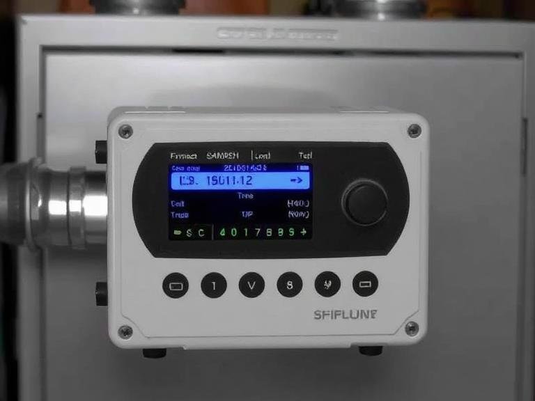
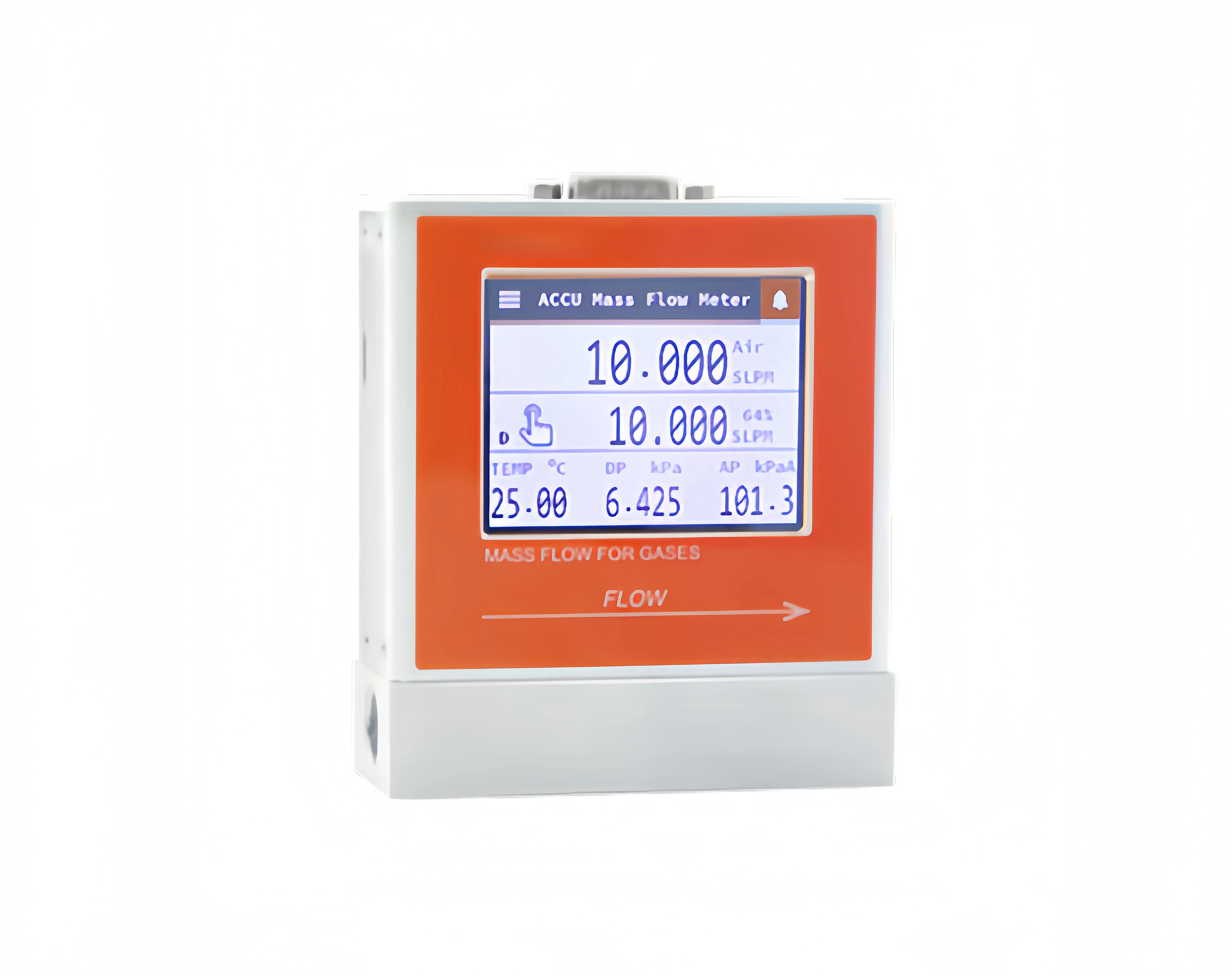
6. Intelligent Sensor and Digital Display Integration
The modernization of industrial facilities demands that instruments communicate vast amounts of diagnostic data. The core of how a gas mass flow controller work today relies heavily on onboard microprocessors. Intelligent sensor technology allows the device to self-diagnose valve wear, monitor sensor drift, and adapt its PID tuning based on sudden line pressure fluctuations.
Furthermore, digital display technology is also widely used in the product series manufactured by Sino-Inst. We recommend utilizing controllers with digital displays for localized process monitoring. A high-resolution digital interface allows operators to change gas types, view real-time flow rates, and alter setpoints directly at the device without requiring a separate computer interface. This integration of digital intelligence is what elevates a basic flow valve into a precision mass flow instrument.
7. Summary Table: Mass Flow Technologies Compared
To assist engineers in determining exactly which technology ensures the gas mass flow controller work best for their facility, we have compiled this comparative summary table.
| Technology Type | Measurement Principle | Key Advantages | Sino-Inst Featured Product |
|---|---|---|---|
| Thermal | Heat transfer via gas flow | No moving parts in sensor, highly reliable, cost-effective | SI-10FA Analog Mass Flow Controller/Meter |
| Differential Pressure (Laminar) | Pressure drop across a laminar flow element | Ultra-fast response time, low pressure drop, multigas capable | SI-30FC Compact DP Mass Flow Controller for Gases |
| Coriolis | Inertial phase shift in a vibrating tube | Direct mass measurement, independent of gas properties, highest accuracy | SI-20FD-HM High Accuracy Mass Flow Meter Ultra-Large Range |
8. Frequently Asked Questions (FAQs)
Why is understanding how a gas mass flow controller work important for calibration?
Because thermal controllers rely on the specific heat capacity of a gas, they are typically calibrated to a single gas (like Nitrogen). If you change the gas, you must apply a specific K-factor to correct the reading. Understanding how the gas mass flow controller work process calculates thermal transfer ensures you apply the correct conversion factor, maintaining process accuracy.
Does orientation affect how a gas mass flow controller work?
From our experience, thermal mass flow controllers are sensitive to orientation due to internal heat convection currents, especially when operating at high pressures. We recommend installing thermal MFCs horizontally. Conversely, DP and Coriolis controllers are generally unaffected by orientation, allowing for flexible installation geometries.
What causes a gas mass flow controller to fail?
The most common failure in any gas mass flow controller work cycle is contamination. Particulates, moisture, or oil from a compressor can clog the fine capillary sensor tubes or damage the proportional valve seating. We strongly recommend installing high-quality particulate and coalescing filters directly upstream of any mass flow instrument.
Can a gas mass flow controller work with liquid?
Thermal and DP controllers are specifically engineered for either gas or liquid, and you cannot interchange them due to drastically different density and thermal properties. However, a Coriolis controller measures true mass regardless of phase, meaning a Coriolis device can often measure both gases and liquids accurately.
9. Industry References
To further your technical understanding of fluid dynamics, automated valve control, and the exact physics of how a gas mass flow controller work, we recommend consulting the following authoritative engineering resources:
- National Institute of Standards and Technology (NIST) – Fluid Metrology and Flow Measurement Standards
- International Society of Automation (ISA) – Instrumentation and Control Loop Guidelines
- International Organization for Standardization (ISO) – ISO/TC 30 Measurement of Fluid Flow in Closed Conduits