.png)
How to connect and use a Sino-Inst thermal gas mass flow controller and a PLC? The connection between a thermal gas mass flow controller (MFC) and a PLC is mainly achieved through electrical signal transmission to read flow data and issue control commands.
Communication between the MFC and the PLC enables real-time monitoring and control of gas or liquid flow rates, improving the stability and reliability of the production process. Through communication, the PLC can acquire the real-time operating status of the MFC, such as parameters like flow rate, pressure, and temperature, and remotely control the MFC as needed. Furthermore, communication can also enable fault diagnosis and alarm functions, allowing for timely detection and handling of problems in the production process.
Our thermal gas mass flow controllers can be configured with either analog or digital signals, such as 0–5V, 4–20mA, 1–5V, RS232/485, and MODBUS protocol. Therefore, the connection between the thermal gas mass flow controller and the PLC needs to be discussed separately based on the signal.

Featured Thermal Gas Mass Flow Controllers


1. Analog Signal Connection
Analog signal connection is simple, reliable, and low-cost.
The PLC’s analog input module receives the MFC’s real-time flow feedback signal, such as 0–5V, 4–20mA, or 1–5V. 4-20mA corresponds to 0%~100% of the measurement range. The PLC’s analog output module sends the setpoint signal to the MFC; similarly, 4-20mA corresponds to the target flow.
Note: 0-5V voltage signals are suitable for short-distance transmission (typically <10 meters), and the wiring method is similar to that of current signals. It should be noted that voltage signals are easily affected by line voltage drops; for long-distance transmission, current signals are preferred.
2. Digital Communication Connection
Digital communication connections offer strong anti-interference capabilities and support multi-device networking. The RS485 Modbus RTU protocol is the most commonly used.
The MFC connects to the PLC’s serial port module via an RS485 interface, supporting multi-point bus topologies. Up to 64 devices can be connected. The PLC acts as the master station, sending Modbus commands, such as function codes to read flow values and write setpoints. RS485 digital communication products are suitable for high-performance scenarios. Both the PLC and MFC must support the corresponding protocol, achieving high-speed data exchange and real-time control through a dedicated interface module.
Whether using analog or digital signals, the wiring requirements are consistent. A four-wire design (power positive and negative + signal positive and negative) is required, ensuring the signal common terminal is correctly grounded to reduce interference.

3. Implementation Steps:
- Hardware Connection: Connect the signal output terminal to the PLC’s input module, such as an analog input module or a digital input module.
- Parameter Setting: Set parameters such as output signal type (analog or digital), signal range, and communication protocol according to actual needs. Simultaneously, set the PLC’s input module parameters, such as sampling rate and data format.
- Programming: Write the PLC program to implement control and data processing. For example, a PID control algorithm can be used to achieve precise flow control; a data processing algorithm can be used to achieve real-time monitoring and alarm functions for parameters such as flow rate and pressure.
- Debugging and Optimization: During actual operation, debug and optimize the PLC program to ensure stable and reliable communication with the PLC, meeting production requirements.
FAQ
Related Products


A thermal mass flow controller is an instrument capable of accurately measuring and controlling gas flow rate, widely used in industries such as petroleum, chemical, metallurgy, and power. A programmable logic controller (PLC), as a widely used control device in industrial automation, possesses powerful functions and flexibility.
Communication between the mass flow controller and the PLC is an important topic in industrial automation. Through proper hardware connection, parameter setting, program writing, and debugging optimization, precise control and real-time monitoring of gas or liquid flow rates can be achieved, improving the stability and reliability of the production process. If you have any technical questions, please feel free to contact us!
More Resources
-
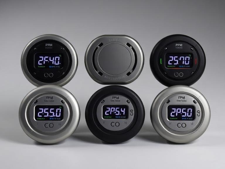
6 Professional Carbon Monoxide Detectors with PPM Displays
Carbon monoxide (CO) is often characterized as the silent killer because it is colorless, odorless, and tasteless. While standard residential alarms are designed…
-
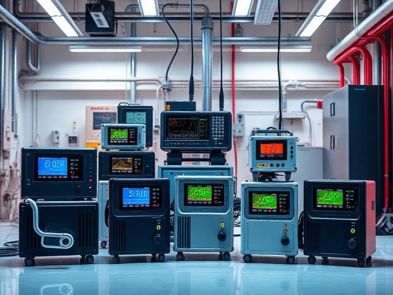
9 Professional Exhaust Gas Analyser Solutions for Industrial Emissions
As industrial regulations tighten globally, the need for precise and reliable emission monitoring has never been more critical. At Sino-Inst, we understand that…
-
7 Professional Indoor VOC Monitoring Equipment Solutions
Authored by Sino-Inst — A globally recognized manufacturer of industrial instrumentation and process control equipment. From our experience engineering robust sensing technologies, protecting…
-
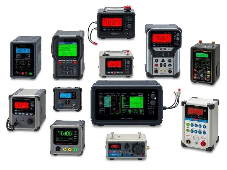
The Ultimate Guide to Flow Controllers Mass Price in 2026
Authored by Sino-Inst — A leading industrial automation and process control instrument manufacturer specializing in precision flow, pressure, and fluid measurement solutions. In…
-
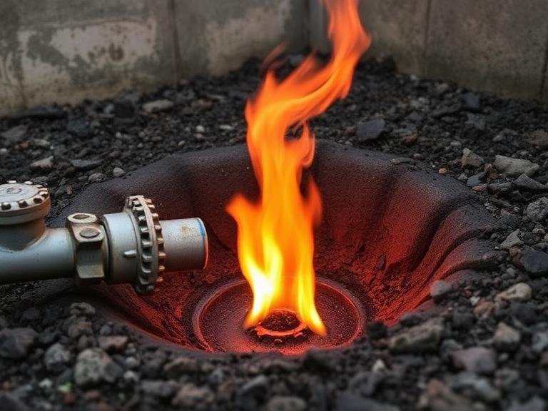
6 Signs of a Natural Gas Leak
Authored by Sino-Inst. We are a professional supplier of industrial process and analytical instruments, including gas detectors, gas analyzers, mass flow controllers, and…
-
The 5 Core Differences Between MFC and MFM
In the realm of process automation, semiconductor manufacturing, and advanced laboratory research, the precise management of gas and liquid flow is not merely…